Chapter 3
M2 Quick start guide
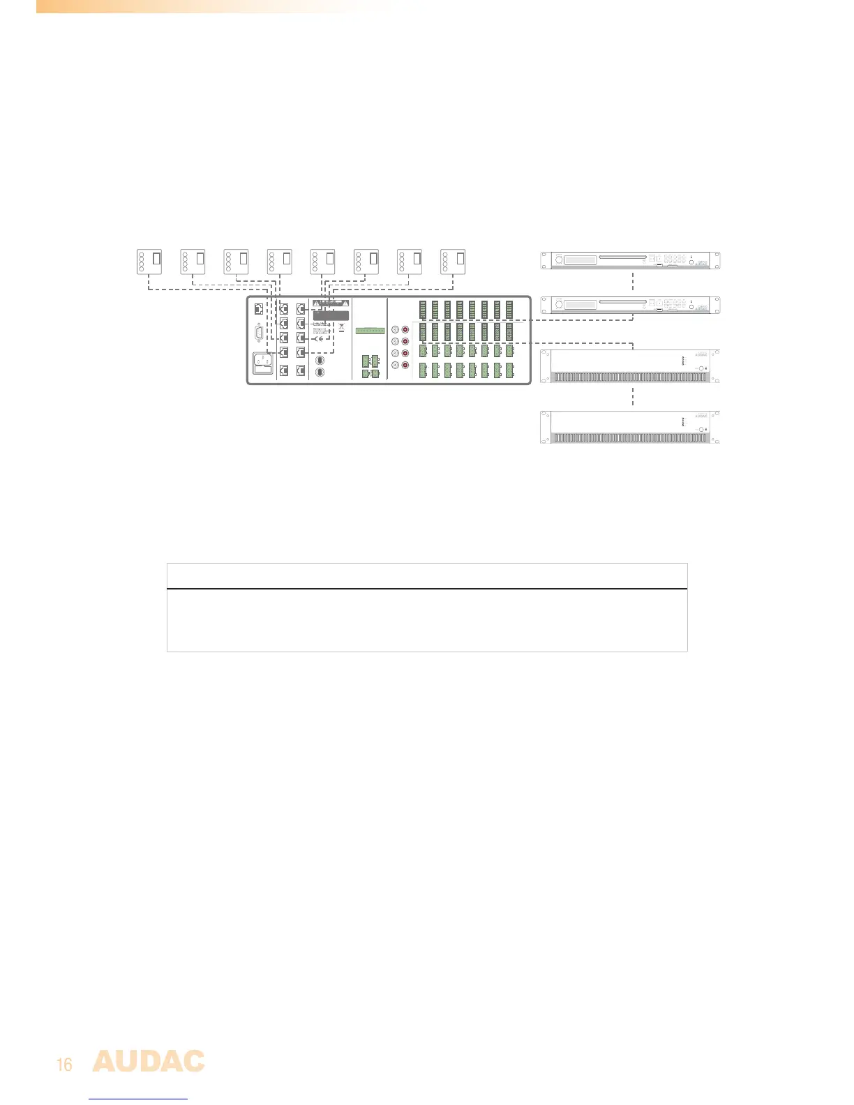
This chapter guides you through the setup process of a basic project using one M2 Mixer with
8 standard DW3020/4020 wall panels and two All-In-One DW5065 wall panels.
Overview of the M2 setup
Connecting the M2
ATTENTION
MakesurethepowerofthedeviceisturnedOFFbeforeanyconnectionsorwiring
adjustmentsaremade.Disregardingthisrulecanleadtopermanentdamageofthe
equipment.
1) Connecting audio sources
ConnectallaudiosourcestotheaudioinputsontherearsideoftheM2.Theseinputsare
BalancedStereoinputsandperformedusing6-pinsterminalblockconnectors,(3-pins
foreachLeftandRightchannel).TheseinputsbothacceptLineandMicrophonelevel
signalsandthegainadjustmentisdoneautomaticallybytheALC.Amonosource(such
asmicrophone)shouldalwaysbeconnectedtotheLeftinputandwhenusingcondenser
microphonesthephantompowershouldbeswitchedON.
2) Connecting amplifiers and/or speakers
Connectamplifiers(100Vorlowimpedance)tothebalancedoutputsoftheM2.These
outputsareperformedusing6-pinsterminalblockconnectors(3-pinsforeachLeftand
Rightchannel).Theamplifierconfiguration(100VorLowimpedance)andpowerneedsto
bechosenaccordingtotherequirementsofeachspecificapplication.Whentheinternal
poweramplifierkit(POW2)isinstalled,lowimpedanceloudspeakersorlinetransformer
unitscanbeconnecteddirectlytotheamplifiedoutputsoftheM2.Theoutputcanbe
switchedbetweenStereo&Mono,orcanbebridgedincasethepoweramplifierkit
(POW2)isinstalled.
Prio rity Inp uts
CH 1
CH 2
Cont act Inp uts
1
2
3
4
5
6
7
8
C
9A
9B
9C
9D
8 7 6 5 4 3 2 1
INPUT
L-
L+
GND
R-
R+
GND
L-
L+
GND
R-
R+
GND
L-
L+
GND
R-
R+
GND
L-
L+
GND
R-
R+
GND
L-
L+
GND
R-
R+
GND
L-
L+
GND
R-
R+
GND
L-
L+
GND
R-
R+
GND
L-
L+
GND
R-
R+
GND
L-
L+
GND
R-
R+
GND
L-
L+
GND
R-
R+
GND
L-
L+
GND
R-
R+
GND
L-
L+
GND
R-
R+
GND
L-
L+
GND
R-
R+
GND
L-
L+
GND
R-
R+
GND
L-
L+
GND
R-
R+
GND
L-
L+
GND
R-
R+
GND
NO
COM
NC
NO
COM
NC
NO
COM
NC
NO
COM
NC
NO
COM
NC
NO
COM
NC
NO
COM
NC
NO
COM
NC
OUTPU T
8 7 6 5 4 3 2 1
R-
R+
L-
L+
R-
R+
L-
L+
R-
R+
L-
L+
R-
R+
L-
L+
R-
R+
L-
L+
R-
R+
L-
L+
R-
R+
L-
L+
R-
R+
L-
L+
Perip heral I nterf aces
RS48 5(1) R S485( 2)
RS48 5(3) R S485( 4)
RS48 5(5) R S485( 6)
RS48 5(7) R S485( 8)
RS48 5(9) RS485( 10)
emote Control
(Ethernet)
(RS232
)
Fuse :
230V ~ /5 0Hz
Link
In
Out
Prog.
Vol
+