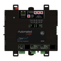
To connect the G5CE to the Ethernet
Connect an Ethernet cable to the Gig-E Ethernet port.
NOTE If your system has controllers on different IP subnets separated by an IP router, you must
configure one controller on each subnet as a BACnet Broadcast Management Device (BBMD). Do not
configure more than one BBMD per subnet as this may cause circular routes. See "Setting up BACnet
Broadcast Management Devices (BBMDs)" in SiteBuilder or WebCTRL® Help.
To wire to a BACnet/ARCNET network
1 Turn off the G5CE's power.
2 Check the communications wiring for shorts and grounds.
3 Connect the communications wiring to Port S1’s screw terminals labeled Net +, Net -, and Shield.
NOTE Use the same polarity throughout the network segment.
4 If the controller has a Port S1 Configuration rotary switch, set it to 2.
5 If the G5CE is at either end of a network segment, set the port's End of Net? switch to Yes.
NOTE The controller’s End of Net switch applies network termination and bias. If the controller is at
the end of a network segment that includes a DIAG485 that has its Bias jumper in the ON position,
set the End of Net? switch to No and connect a 120 ohm termination resistor to the Net+ and Net-
terminals. See DIAG485 Technical Instructions for more information.
6 Turn on the controller's power.
7 To verify communication with the network, get a Module Status report in the WebCTRL® interface
for a controller on the ARCNET network.
NOTE This step requires that you have set up the router in SiteBuilder and downloaded it from the
WebCTRL® interface.
To wire to a BACnet MS/TP network
An MS/TP network can be wired to either Port S1 or Port S2.
1 Turn off the G5CE's power.
2 Check the communications wiring for shorts and grounds.
3 Connect the communications wiring to the Port S1 or Port S2 screw terminals labeled Net +, Net -,
and Shield.
NOTE Use the same polarity throughout the network segment.
4 If you are using Port S1, and the controller has a Port S1 Configuration rotary switch, set it to 1.
NOTE If Port S1 is not being used for any network, set this rotary switch to 0.
5 If the G5CE is at either end of a network segment, set the port's End of Net? switch to Yes.
NOTE The controller’s End of Net switch applies network termination and bias. If the controller is at
the end of a network segment that includes a DIAG485 that has its Bias jumper in the ON position,
set the End of Net? switch to No and connect a 120 ohm termination resistor to the Net+ and Net-
terminals. See DIAG485 Technical Instructions for more information.
6 Turn on the controller's power.
7 To verify communication with the network, get a Module Status report in the WebCTRL® interface
for a controller on the MS/TP network.
NOTE This step requires that you have set up the router in SiteBuilder and downloaded it from the
WebCTRL® interface.

 Loading...