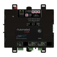
OptiFlex™ BACnet Integrator (part no. G5CE) Automated Logic Proprietary and Confidential A Carrier Company. © 2022 Carrier.
Rev. 6/9/2022 All rights reserved.
8
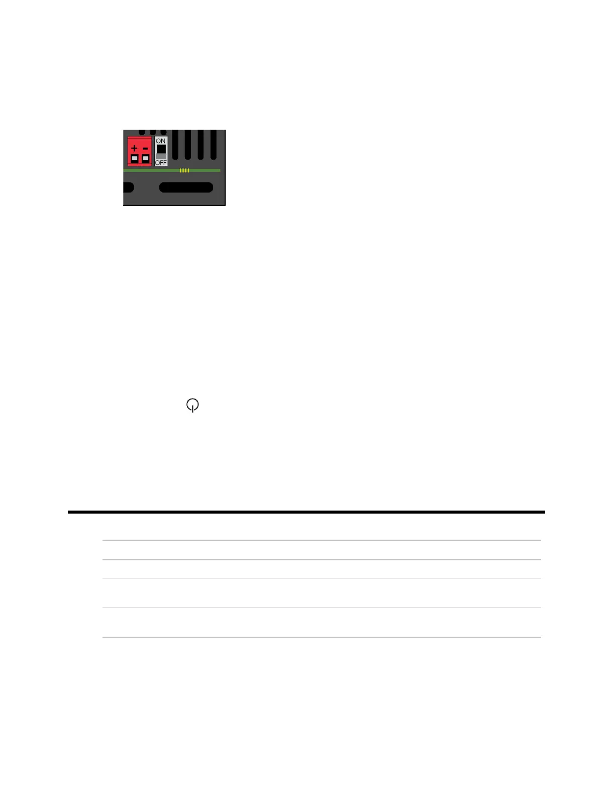
To wire for power
1 Make sure the G5CE’s power switch is in the OFF position to prevent it from powering up before you
can verify the correct voltage.
2 Remove power from the power supply.
3 Pull the red screw terminal connector from the controller's power terminals labeled 24 Vac/Vdc
(+/-).
4 Connect the power supply's wires to the red screw terminal connector.
5 Connect an 18 AWG or larger wire from the power supply's negative (-) terminal to earth ground.
This wire must not exceed 12 in. (30.5 cm).
6 Apply power to the power supply.
7 Measure the voltage at the red screw terminal connector to verify that the voltage is within the
operating range of 20 to 30 Vac or 23.4 to 30 Vdc.
8 Insert the red screw terminal connector into the controller's power terminals.
9 To verify the polarity of the wiring, measure the voltage from the negative terminal of the red screw
terminal connector to a nearby ground. The reading should be 0V.
10 Turn on the expander's power switch.
11 Verify that the LED on top of the controller is on.
12 Measure the voltage at the red screw terminal connector to verify that the voltage is within the
operating range of 20 to 30 Vac or 23.4 to 30 Vdc.
Addressing the G5CE
 Loading...