OptiFlex™ BACnet Integrator (part no. G5CE) Automated Logic Proprietary and Confidential A Carrier Company. © 2022 Carrier.
Rev. 6/9/2022 All rights reserved.
7
2 Place the controller on the DIN rail so that the rail is in the trough on the back of the controller.
3 Push the center tabs towards the controller until you hear them click.
4 Pull gently on the controller to verify that it is locked in place.
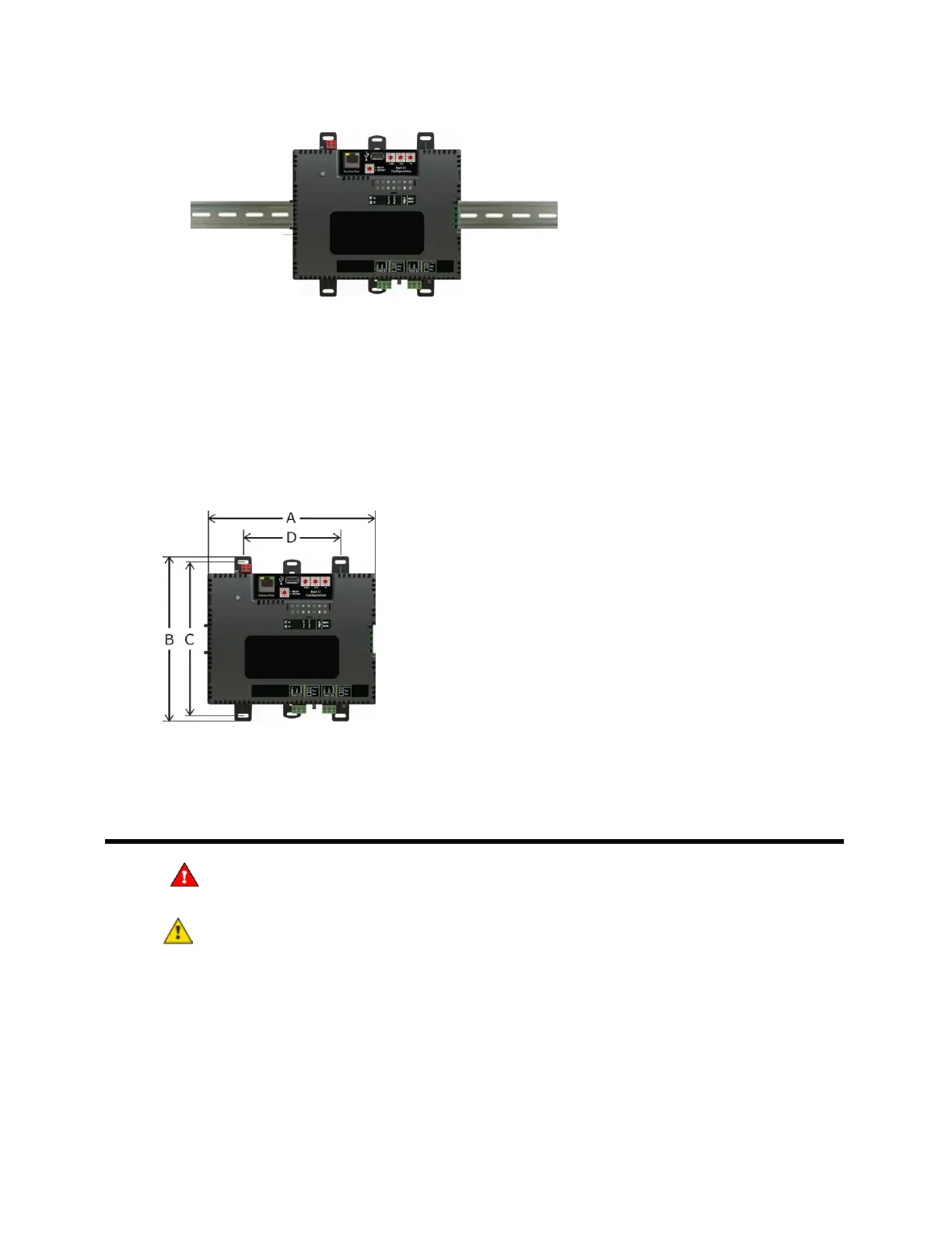
Screw Mount
Leave about 2 in. (5 cm) on each side of the controller for wiring.
Insert #6 screws through the mounting holes. Use no more than 8 in.lbs. torque to secure plastic tab to
mounting surface.
7.1 in. (18.03 cm)
6.95 in. (17.65 cm)
6.45 in. (16.38 cm)
4.1 in. (10.4 cm)
2.09 in (5.31 cm)
Wiring for power
WARNING Do not apply line voltage (mains voltage) to the controller's ports and terminals.
CAUTIONS
• The G5CE is powered by a Class 2 power source. Take appropriate isolation measures when
mounting it in a control panel where non-Class 2 circuits are present.
• Automated Logic® controllers can share a power supply as long as you:
○ Maintain the same polarity.
○ Use the power supply only for Automated Logic® controllers.
 Loading...