User Constructed Cables – Wiring Diagrams (cont’d)
Diagram 20
Diagram 21
6–34
Chapter 6: PLC Communications
6
EA1-TCL-M Hardware User Manual, 2nd Ed., 10/10
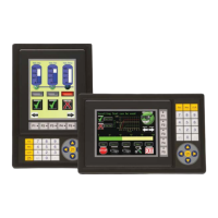
GS Serial Drive Connection via RS-485
RD–
SD–
shield
Wiring Diagram
SD+
RD+
GND
TERM
Note: Use the above wiring diagram to make your own cable. We recommend Belden 8102 shielded cable or equivalent.
EA-COMCON-3
C-more Micro-Graphic
Serial Port2
61
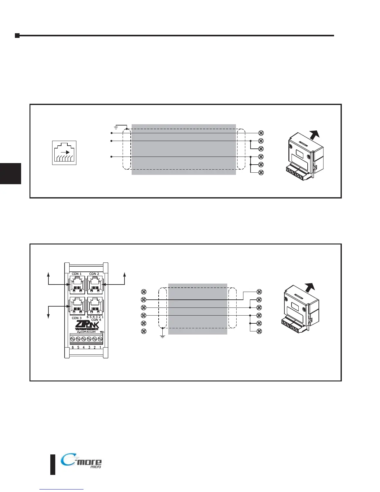
GS Drives RS-485
Serial Comm. Port
2: GND
3: SG –
4: SG +
RD –
SD –
shield
Wiring Diagram
SD +
RD +
GND
TERM
Notes: 1. The terminal connections at the ZL-CDM-RJ12X4 are different for multi-drop networks than for the direct
drive to panel connection.
2. Use the above wiring diagram to make your own cable. We recommend Belden 9842 shielded cable or equivalent.
EA-COMCON-3
Multiple GS Drives Connected to One C-more Micro-Graphic panel (RS-485)
TB1
1
2
3
4
5
6
C-more Micro-Graphic
Serial Port2
*Connect with ZL-RJ12-CBL-2P cable
*
GS3
GS Drive 6-Pin
RJ12 port
GS1
GS Drive 6-Pin
RJ12 port
GS2
GS Drive 6-Pin
RJ12 port
*
*
 Loading...