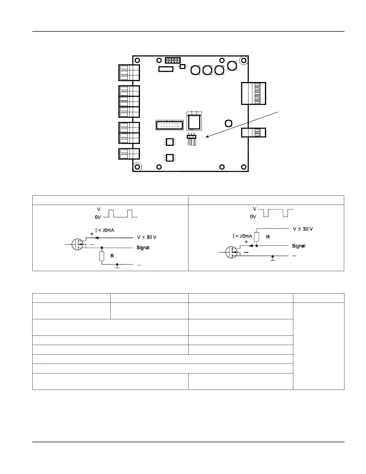
Jumper Location
JP2
JP1
JP1 jumper for
Figure 34: JP1 location
Digital Output Wiring Diagrams
Positive Pulse Logic Negative Pulse Logic
Figure 35: Digital output wiring diagram
Digital Output Selections
Output 1 Output 2 Output 3 Output 4
Forward Pulse Output Reverse Pulse Output
Flow direction
(Forward vs. Reverse)
ADE
Flow Setpoint
(0…100% of full scale, resolution 1%)
Flow Setpoint
(0…100% of full scale, resolution 1%)
Empty pipe alarm Empty pipe alarm
Error alarm Error alarm
Off
Test
Can be used with AMR when the pulse width is set to
50 milliseconds.
—
Outputs are configurable for Pulses/Unit (PPU) and Pulse Width (PW). The PW is configurable from 5…500 milliseconds, with a
frequency limit of 100 Hz. PPU displays using an automatically selected resolution.
The high/low flow alarm functionality is configurable for maximum and minimum setpoints as a percentage of full-scale flow.
Configurable values are settable from 0…100% in 1% increments.
=
Conguring Input/Output (I/O)
MAG-UM-00219-EN-17 Page 23 June 2021