CONFIGURING INPUT/OUTPUT I/O
This section describes wiring the following M5000 outputs:
• Digital outputs
• Communication
When the sensor and the amplifier have been wired, wire any outputs to the M5000 amplifier.
Follow all of the safety precautions and local code to prevent electrical shock and damage to the electronic components.
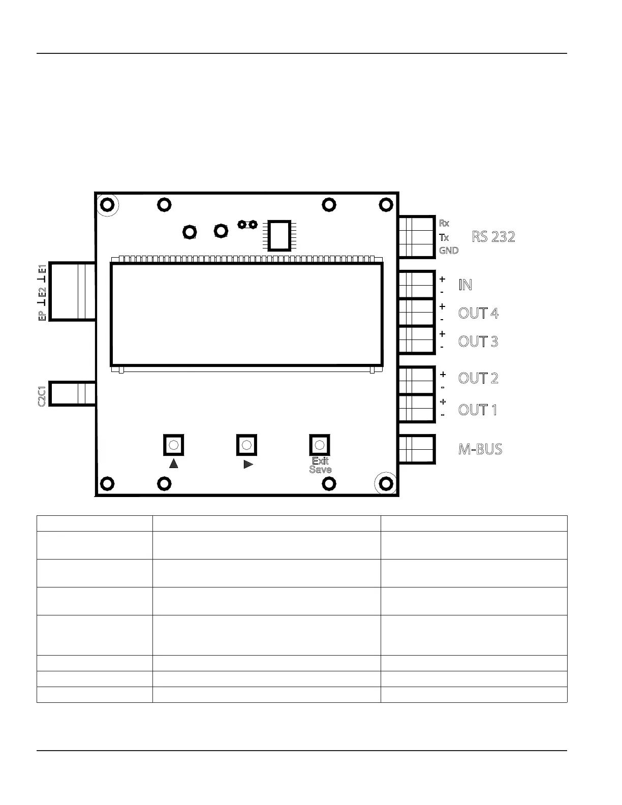
Circuit Board Diagram
Exit
Save
Tx
Rx
GND
IN
OUT 2
M-BUS
OUT 1
OUT 3
OUT 4
+
-
+
-
+
-
+
-
+
-
Figure 33: Configuring input/output
Input/Output Description Terminal
Output 1 Passive maximum 30V DC, 20 mA
Maximum frequency 100 Hz
OUT1 (+) and (–)
Output 2 Passive maximum 30V DC, 20 mA
Maximum frequency 100 Hz
OUT2 (+) and (–)
Output 3 Passive maximum 30V DC, 20 mA
Maximum frequency 100 Hz
OUT3 (+) and (–)
Output 4 Passive maximum 30V DC, 20 mA
Maximum frequency 100 Hz
Can be used with digital input as an ADE interface.
OUT4 (+) and (–)
RS232 Modbus RTU RxD, TxD, GND
IN Digital input 3…35V DC IN (+) and (–)
M-Bus M-Bus interface No polarity
OTE: N The M5000 meter also supports Modbus RTU RS485 communication. Modbus RTU communication options must be
selected at time of order or can be ordered as a service part. See the “M5000 Modbus Communication Protocol Memory
Map Application Data Sheet”, available at www.badgermeter.com.
Conguring Input/Output (I/O)
MAG-UM-00219-EN-17Page 22 June 2021