SYSTEM DESCRIPTION
The Badger Meter model M5000 electromagnetic flow meter is intended for fluid metering in most industries including
potable water, reclaimed water, food and beverage, pharmaceutical and chemical. The meter can measure all fluids with
electric conductivity of at least 5 µS/cm (20 µS/cm for demineralized water) and is highly accurate. Measuring results depend
on density, temperature and pressure.
The basic components of an electromagnetic flow meter are:
• The detector, which includes the flow tube, isolating liner and measuring electrodes.
• The amplifier, which is the electronic device responsible for the signal processing, flow calculation, display and
outputsignals.
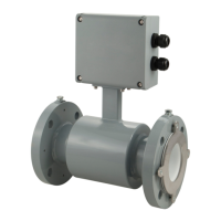
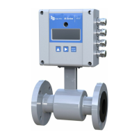
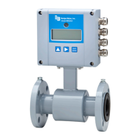
Figure 4: Amplifier and detector
The construction materials of the wetted parts (liner and electrodes) should be appropriate for the specifications on the
intended type of service. We recommend that you review all of the compatibilities consistent with the specifications.
Each meter is factory tested and calibrated. A calibration certificate is included with each meter.
OPERATING PRINCIPLE
In accordance with Faraday’s induction principle, electric voltage is induced in a conductor moving through a magnetic
field. In case of the electromagnetic flow measurement, the moving conductor is replaced by the flowing fluid. Two opposite
measuring electrodes conduct the induced voltage which is proportional to flow velocity to the amplifier. Flow volume is
calculated based on pipe diameter.
AMPLIFIER MOUNTING CONFIGURATION OPTIONS
Meter Mounted Conguration
The meter mount configuration has the amplifier mounted directly on the detector. This compact, self-contained
configuration minimizes installation wiring.
Remote Mount Conguration
The remote mount configuration places the amplifier at a location away from the fluid flow and detector. This is necessary in
situations where process fluid temperature or the environment exceeds amplifier ratings.
The detector and amplifier are connected by wires, run through conduit, between junction boxes on the detector and the
amplifier. The distance between the detector junction box and amplifier junction box can be up to 100 feet (30 meters). A
remote mounting bracket is supplied.
Submersible Option
If you are installing the meter in a vault, order the remote amplifier option. Do not install the amplifier inside a vault. We also
recommend ordering the remote meter package with the submersible option (NEMA 6P/IP68) to eliminate any potential
problems resulting from humidity or temporary flooding in the vault.
OTE: N NEMA 6P/IP68 enclosures are constructed for indoor or outdoor use to provide protection against access to
hazardous parts, and to provide a degree of protection against ingress of solid foreign objects and water (hose
directed water and the entry of water during prolonged submersion at a limited depth). They provide an additional
level of protection against corrosion and are not damaged by the external formation of ice on the enclosure.
System Description
MAG-UM-00219-EN-17Page 8 June 2021
 Loading...


