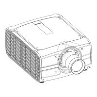
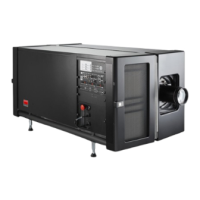
R5906788-03 Thor series50
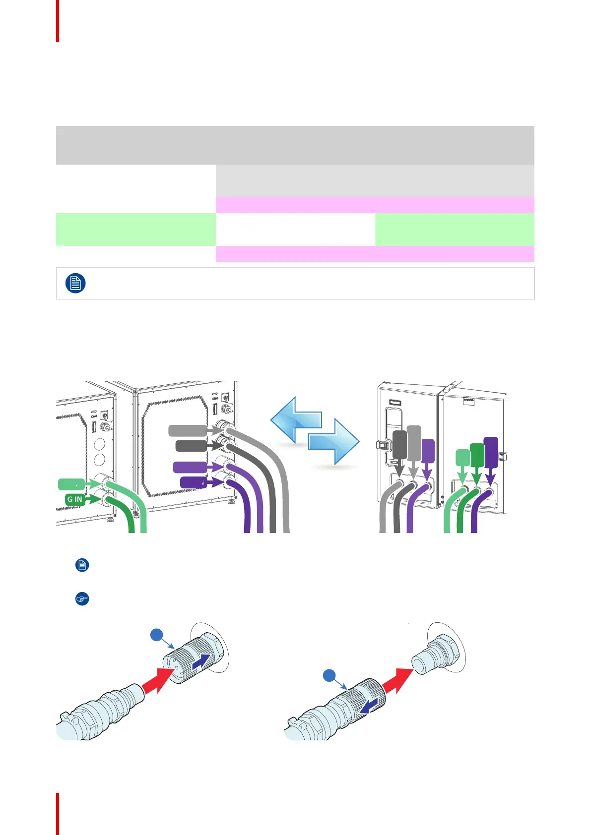
Hoses IN/OUT connection scheme
The labels on the projector and on the chiller indicating the three different cooling circuits: (R/B, G and DMD)
and the direction of the liquid flow: OUT and IN. 'OUT' means liquid flows out of the chiller or projector, 'IN'
means liquid flows into the chiller or projector. Both sides of all hoses are also labeled.
Chiller without DMD cooling
unit
(not for Thor)
Chiller with DMD cooling unit Projector
DMD OUT DMD IN
DMD IN DMD OUT
R/B OUT R/B IN
G OUT G IN
G IN G OUT
R/B IN R/B OUT
The Thor series projector requires only one chiller. The circuits G-IN and G-OUT are omitted.
How to connect the hoses?
1. Ensure that all connectors of the hoses, chillers and projector are clean. Wipe away any dust before attaching.
2. Connect the hoses one by one with the chiller and projector as illustrated below. (see also 'IN/OUT connection
scheme' above)
R/B IN
R/B OUT
G OUT
R/B IN
D
MD OUT
Image 6-7
Note: The circuit is pressurized which makes it sometimes difficult to insert the hoses.
Tip: First move the latch (reference 1 Image 6-8) away from the connection while coupling the hose.
Then release the latch and push the hose further until the latch locks.
Image 6-8: Left: Male hose connection, right: Female hose connection
Physical installation
 Loading...