4. Theory of Operation
4-45
5. Miscellaneous Modules
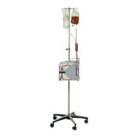
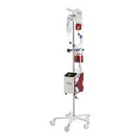
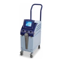
The support housing holds all the components/modules. The left side cover holds
two (2) 12 volt sealed lead acid batteries and the pole clamp mechanism. The
door holds one of the heater assembly ferrite pole pieces. Some of the
components are listed below:
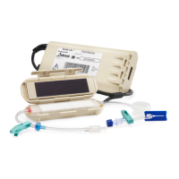
The heater components: ferrite pole pieces, bobbin, heater winding and heater
housing are arranged in the device so that when the heat exchanger (part of the
disposable set) is put in place and the door is closed, the assembly forms a
transformer. The magnetic flux, in the transformer, is generated by applying AC
voltage to the heater winding which induces flux in the ferrite bobbin. The ferrite
bobbin is physically aligned with the ferrite pole pieces, which carry the flux out
around the heat exchanger and collimate it so that the rings in the heat
exchanger enclose the magnetic field. An electric current is generated in the
rings, warming them by virtue of their electrical resistivity. This, in turn, warms
the fluid by conduction. The heater winding is electrically isolated from the heat
exchanger and the ferrite pieces by solid plastic walls. The housing of the
disposable set heat exchanger is also constructed of plastic which insure patient
isolation even if the heater winding should crack. One of the ferrite pole pieces
mounts to the door and the other piece, along with the bobbin, heater winding,
and heater housing are mounted in the support housing.
The membrane panel switch (touch screen), for user interface, contains a
transparent area through which the display is viewable, and a 4 x 4 matrix of
buttons. The buttons are overlaid on the bottom four-fifths of the screen. A
graphic boarder contains the company name and logo, along with the system
trade name. An ESD/EMI conductive layer is incorporated into the panel, and is
electrically tied to chassis ground.
The roller pump is a peristaltic type using four rollers. Each roller is held into a
roller block by a pin upon which it is allowed to roll freely. The roller blocks are
mounted to the pump hub that is attached to the shaft of a gear head motor. The
roller blocks are mounted with a pin at one end, and are supported at the other
end by a spring mounted plunger. The spring applies enough force to the roller
so as to completely pinch the tubing. The pump hub is attached to the gear head
shaft by a shaft coupler, which allows the pump head to be removed with a single
screw for easy cleaning. The 35:1 gear head ratio is used to reduce the speed of
the motor and increase torque. The motor is a brushed motor with an optical
encoder. The encoder is a two-phase device that allows for both speed and
directional sensing. Although the driver circuit can only drive the motor in one
direction, the speed and direction measurement circuitry can detect if the motor
has been connected backwards.