ATICS-2-ISO_D00046_04_M_XXEN / 03.2021 27
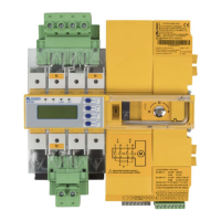
ATICS-2-63A-ISO
234
115
15
220
245
18
1)
222
47
D
132
132
176
176
46
75
52
45
4 Mounting and connection
I
risk of electrocution due to electric shock!
Touching live parts of the system carries the risk of electric shock. Before installing the device and pri-
or to working on the device connections, make sure that the power supply has been disconnected.
Observe the rules for working on electrical installations.
i
Disturbance due to loud switching noise! Install the ATICS® in a closed electrical operating area or in
a sound-proof distribution board.
4.1 Mounting
ATICS® is suitable for DIN rail mounting or screw mounting on a plate. To guarantee protection against
accidental contact, it must be installed behind a plastic cover.
4.1.1 Dimension diagram
A Front view
B Side view
C Rear view (dimensions for screw mounting on mounting plate)
D Adapt the cutout to the terminal cover
1) Auxiliary contacts to be mounted optionally