28 ATICS-2-ISO_D00046_04_M_XXEN / 03.2021
Mounting and connection
Required tools
Use the following tools to connect the power unit and the control cables:
• Torx® screwdriver T20 or 6.5 x 1.2 mm
• Screwdriver 2.5 x 0.4 mm
• Allen key 4 mm
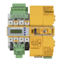
4.1.2 Removing terminal cover
4.1.3 DIN rail mounting
I
Caution! Screws must be tightened, otherwise the vibrations generated during switching may
damage the ATICS®.
1. Push back the locking hook (B) in the middle
of the top and bottom terminal cover (A) by
using a screwdriver.
2. Remove the terminal cover.
N
1. Place the ATICS® on the top edge of the rail.
2. Use a screwdriver to pull down the lower yellow
slide lock (C) and snap the ATICS® into place with
slight pressure. Check that the slide lock has
properly snapped into position by pulling slight-
ly the lower part of the enclosure.
3. Fix all terminals with Allen screws terminals.
Tightening torque: 5 Nm.
4. Fasten the terminal covers.
5. Tighten screws (D) (PZ1, 8,8 lb-in, 1 Nm).