ATICS-2-ISO_D00046_04_M_XXEN / 03.2021 29
ATICS-2-63A-ISO
4.1.4 Screw mounting on plate
i
• Observe dimension diagram of rear view.
• Use M5 mounting screws
I
Caution: Screw heads or washers reduce voltage clearances. Provide for sufficient clearance to live
conductors (voltage clearance) by using mounting screws with flat screw heads and flat washers. If
mounted on electrically conductive material: The mounting plate has to be earthed and the area un-
der the terminals has to be covered with insulating material.
4.2 Connection
4.2.1 Short-circuit protection
When choosing the fuses in the supply lines and outgoing feeders of the transfer switching devices, ob-
serve the requirements of DIN VDE 0100-710 (VDE 0100 Part 710).
• Transformers for the IT system: Where transformers, their primary supply conductor and sec-
ondary outgoing line are concerned, overcurrent protective devices are only permitted for
short-circuit protection. The transformer supply line from the transfer switching device and
the transformer outgoing line to the next distribution board section should be installed
short-circuit and earth-fault proof: (Halogen-free, flexible single-core rubber cable NSHXAFö
1.8/3 kV).
• Protection of the cable system in group 2 medical locations: When choosing protective devic-
es, it is essential to ensure that when the prospective short-circuit currents occur, the protec-
tive device upstream of a fault will selectively trip the protective devices which are further up-
stream.
• Connecting several load groups downstream of an automatic transfer switching device must
not lead to all the load groups failing in the event of a fault.
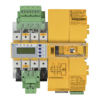
!
1. Undo the Allen screws of the terminals (C).
2. Remove the green plug connectors (D) top and bot-
tom.
3. Remove the black bridge (E) bottom.
4. Fasten the ATICS® to the mounting plate with M5
mounting screws (22 lb-in, 2.5 Nm) (see dimension
diagram).
5. Insert the black bridge (E), bottom.
6. Plug in the green plug connectors (D) top and bot-
tom.
7. Fix all terminals (C) with Allen screws.
Tightening torque: 5 Nm.
8. Fasten the terminal covers.
C
E
N