30 ATICS-2-ISO_D00046_04_M_XXEN / 03.2021
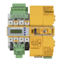
Mounting and connection
As a result, the choice of back-up fuses F should ensure both short-circuit protection for the transformer
and the selectivity to overcurrent devices downstream of the IT systems.
When choosing back-up fuses, observe both the maximum permissible values in accordance with the
applicable local regulations and national and international standards to make sure that the contacts are
weld-free. The considerations presented below are based on the standard DIN VDE 0100-710 (VDE
0100-710).
Selecting a fuse for only one load:
The circuit has only one load, the "IT system trans-
former". Refer to the information provided by the
transformer manufacturer for the minimum size of
back-up fuses for the IT system transformer cho-
sen.
The rated operational current of the ATICS® must
be greater than or the same as the rated operation-
al current of the transformer. Refer to the technical
specifications of the ATICS® for the maximum size
of back-up fuses F1 or F2.
Selecting a fuse for several loads
This circuit branches into several load groups. This
means that each fuse of each load group is moved
downstream of the automatic transfer switching
device. However, the maximum possible back-up
fuse is calculated in the same way as described
above.
The back-up fuse (F1 or F2) must match the back-
up fuse F3 (and of course F4 and F5) so that selec-
tive shutdown is ensured. The back-up fuse speci-
fied by the manufacturer for the IT system trans-
former must therefore be at least two steps
smaller than the back-up fuse determined for the
ATICS® according to the above method.
Of course, the total current rating for the automat-
ic transfer switching device must be calculated from the sum and simultaneity factor of all the load
groups connected and the required or minimum rated current calculated according to the method
above.
ATiCS
F1 F2
Circuit breaker
2
2
M
ATiCS
Circuit breaker
F1 F2
F3 F4
F5
2
2
M