ATICS-2-ISO_D00046_04_M_XXEN / 03.2021 75
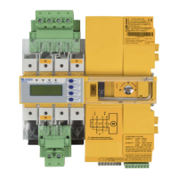
ATICS-2-63A-ISO
Menu Description
Exit Exit settings menu "Voltage"; go up one menu level
1. Functions
I
note: A parameter change can result in an immediate changeover.
off Digital input disabled
M/A Manual/Automatic. Manual mode means that automatic
changeover can no longer take place.
Bypass Alarm "Bypass operation" but TEST changeover possible
no2->1 Switch-back lock. After switching to line 2, the changeover
switch remains in this switch position. It remains there even
when line 1 returns. Switching back to line 1 only takes place
when the digital input is no longer set, line 2 fails or the "RESET"
button has been pressed. The display shows the operating
message "Switch-back lock".
1<->2 Changes the preferred line
TEST A test changeover is carried out. In generator mode, the genera-
tor start relay is also switched. The test is completed when the
output is reset.
ALARM Generates a "Digital input alarm". An alarm relay of an external
ISOMETER® can be connected here. The alarm message appears
on the display and is passed on via the BMS bus. The alarm relay
switches when adjusted accordingly. The alarm message has no
effect on the changeover function.
OPL Generates an alarm "Insulation fault, operating theatre light".
Other functions as for the setting "ALARM".
2. Resp. value 0V At 0 V input is set. The selected function is carried out.
24V At 24 V input is set. The selected function is carried out.
3. t(on) Response delay:
Setting range: 100 ms…100 s
Resolution of settings: starting at 50 ms
4. t(off) Delay on release:
Setting range: 100 ms…100 s
Resolution of settings: starting at 50 ms
7.3.4.7 Settings menu 7: Data loggers