Safety instructions
12
isoxx1685Dx-x25_D00272_07_M_XXEN/09.2022
2.3 Device-specific safety instructions
2.4 Intended use
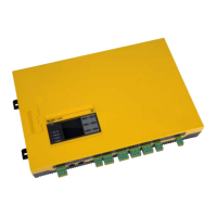
The device is used for monitoring the insulation resistance in large power supply systems de-
signed as IT systems. The specific measurement method AMP
PLUS
monitors the insulation re-
sistance also in installations where extremely high system leakage capacitances to earth exist
due to interference suppression methods. Adaptation event to high leakage capacitances is
automatic.
The device generates locating current pulses required for insulation fault location. That allows
the localisation of the insulation fault using permanently installed or mobile insulation fault
locators.
Intended use also implies:
• The observation of all information in the operating manual
• Compliance with test intervals
In order to meet the requirements of applicable standards, the equipment must be adjusted
to local equipment and operating conditions by means of customised parameter settings. Ple-
ase heed the limits of the range of application indicated in the technical data.
In the "Fast 2000 µF" profile, the iso1685DP can be used in photovoltaic systems.
Any other use than that described in this manual is regarded as improper.
Installation inside a control cabinet
If the ISOMETER® is installed inside a control cabinet, the insulation fault
message must be audible and/or visible to attract attention.
IT systems with several ISOMETER®s
Make sure that only one active ISOMETER® is connected in each
interconnected system. If IT systems are interconnected via coupling switches,
make sure that ISOMETER®s not currently used are disconnected from the IT
system and deactivated. For IT systems coupled via diodes or capacitances a
central control of the different ISOMETER®s is required.
Prevent measurement errors!
When a monitored IT system contains galvanically coupled DC circuits, an
insulation fault can only be detected correctly if the rectifier valves (e.g.
rectifier diode, thyristors, IGBTs, frequency inverters, …) carry a minimum
current of > 10 mA.
Unspecified frequency range
When connecting to an IT system with frequency components below the
specified frequency range, the response times and response values may differ
from the indicated technical data. However, depending on the application
and the selected measurement method, continuous insulation monitoring is
also possible in this frequency range.

 Loading...


