Settings
44
isoxx1685Dx-x25_D00272_07_M_XXEN/09.2022
8.2 Settings in the device menu
8.2 (1 ) Alarm settings
The limit values for the insulation resistances of alarm 1 and alarm 2 can be specified in the
alarm settings menu and the profile of the ISOMETER® can be adjusted. If the password query
has been enabled in the device menu (refer to "Password" on page 65), enter the device pass-
word in order to change the settings.
The following functions can be adjusted:
8.2 (1.1) Insulation alarm
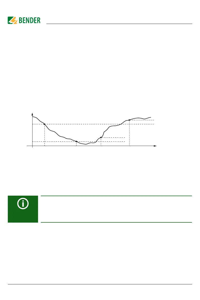
In the Insulation alarm menu, the ISOMETER® limit values for alarm 1 and alarm 2 can be set.
Activation or deactivation of the two alarm levels R
an1
for alarm 1 and R
an2
for alarm 2 are il-
lustrated in the following graphic:
An alarm will become inactive as soon as the hysteresis of the set operating value is exceeded.
8.2 (1.1.1) Alarm 1
An insulation resistance of 200 …1 M can be set for alarm 1.
Condition: alarm 1 ≥ alarm 2.
8.2 (1.1.2) Alarm 2
An insulation resistance of 200 …1 M can be set for alarm 2.
8.2 (1.1.3) Fault memory
Automatic reset of inactive faults at the outputs
(relays 11-12-13, 21-22-24):
Response value ranges
The response value range depends on the device variant. For further infor-
mation on the response value ranges of individual variants, refer to chapter
12. "Technical data" from page 75.
•on If a fault becomes inactive, the programmed outputs remain in fault
condition until they are reset manually.
•off If a fault becomes inactive, the programmed outputs automatically
change their state.
t
R
R
an1
R
an2
Alarm 1
aktiv
Alarm 2
aktiv
Hysterese
Alarm 1
inaktiv
Hysterese
Alarm 2
inaktiv