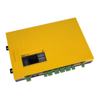
Insulation fault location (isoxx1685DP only)
73
isoxx1685Dx-x25_D00272_07_M_XXEN/09.2022
10. Insulation fault location (isoxx1685DP only)
10.1 General description
An additional function of the ISOMETER® in combination with the EDS is the selective insulati-
on fault location. The insulation faults detected in the IT system by the ISOMETER® can be lo-
cated by means of an EDS and measuring current transformers. For further information
regarding the operating principle of the insulation fault location, refer to 3.3.2 "Insulation fault
location" on page 15.
10.2 Required settings for insulation fault location
Connecting and commissioning the system consisting of ISOMETER® and EDS correct-
ly
For further information regarding the connection of the EDS, refer to chapter 5.2.3 "Connec-
ting the EDS to the ISOMETER® isoxx1685DP" from page 25, and to the corresponding manual
of the EDS.
Setting locating current and EDS mode
These settings can be made either during initial commissioning
(see chapter 6.3 "Initial commissioning" from page 31) or in the device menu of the ISOMETER®
(see chapter 8.2 (2 ) "EDS (insulation fault location only for isoxx1685DP)" from page 50).
For further information regarding the locating current for insulation fault location, refer to 8.2
(2.1.2) "Current" on page 51.
For further information regarding EDS modes, refer to 8.2 (2.1.1) "Mode" on page 50.
10.3 Indication on the display
The active insulation fault location is shown on the display of the ISOMETER®.
For further information, refer to chapter 7.7 "Insulation fault location" from page 40.
10.4 Starting and stopping the insulation fault location
The insulation fault location can be started and stopped via different interfaces:
• Shortcut button "EDS". Permanently start/stop the insulation fault location manually. If
the device is started permanently, it will measure until it is stopped manually using the
shortcut button. (refer to chapter 4.3 "Display and operating elements" from page 20)
• Device menu
• Digital input
For further information regarding start and stop conditions of the insulation fault location, re-
fer to 8.2 (2.1.1) "Mode" on page 50.

 Loading...


