Display
37
isoxx1685Dx-x25_D00272_07_M_XXEN/09.2022
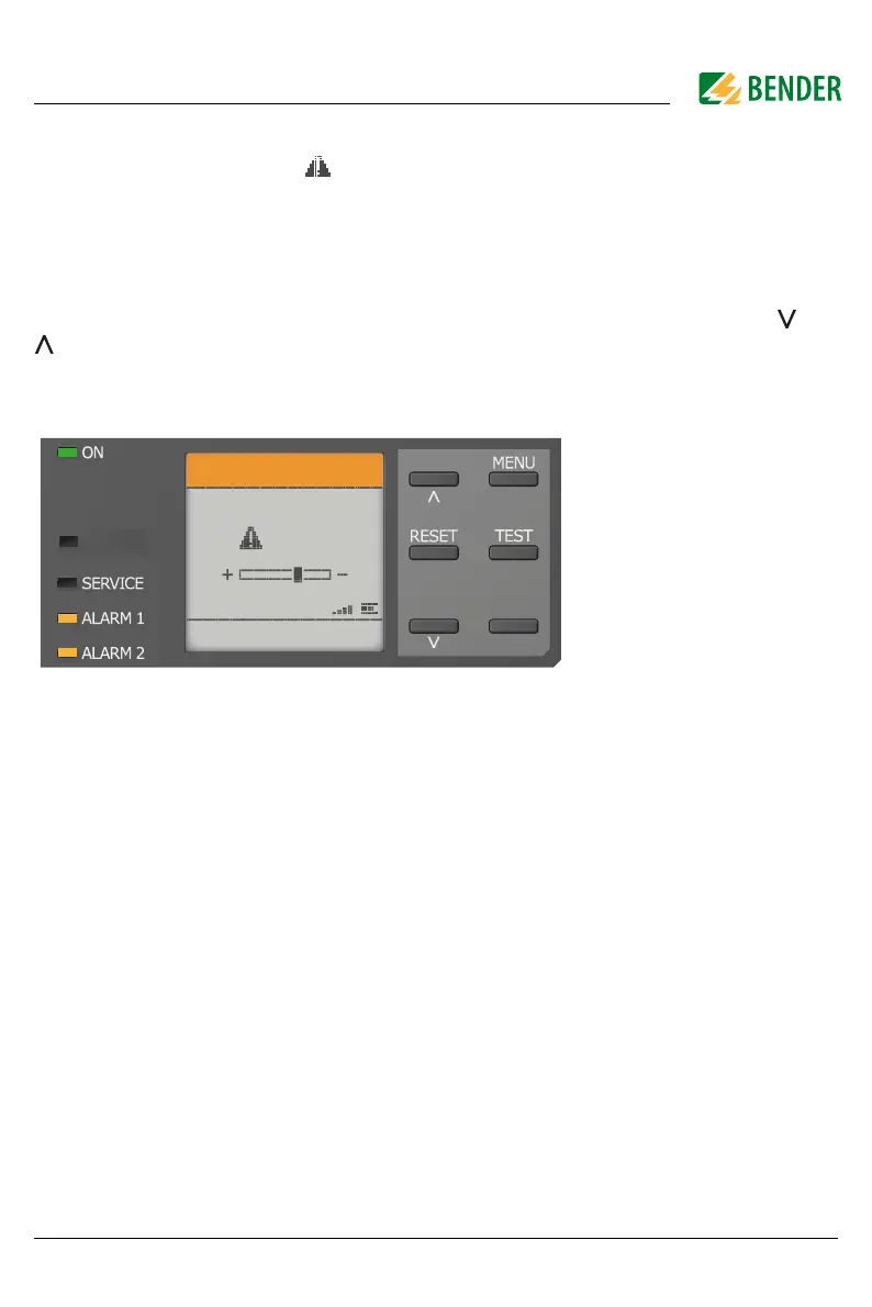
7.2 Fault display (active)
An active fault is displayed by .
The upper part of the display turns orange and displays the fault message.
Depending on the type of fault, the LEDs "ALARM 1", "ALARM 2" or "SERVICE" are activated.
In the following example, a resistance has been detected. Since the values R
an1
=40 kΩ and
R
an2
=10 kΩ are both below the set response value, „ALARM 1“ and „ALARM 2“ have been trig-
gered.
If several fault messages have appeared, you can navigate through the faults using the and
buttons.
If the value falls below R
an1
in a DC system or a DC offset is detected in an AC system, additional
detailed information regarding the DC offset will be displayed.
PGH ON