Settings
42
isoxx1685Dx-x25_D00272_07_M_XXEN/09.2022
8. Settings
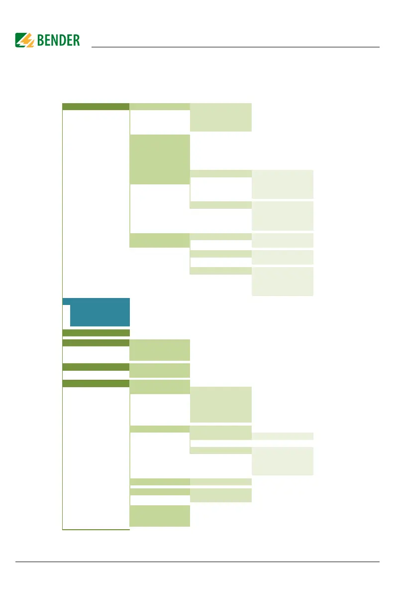
8.1 Device menu structure
1) The numbering of the menu items differs for the models isoHV1685D-425 and isoHR1685D-925 from
menu item 3 (Data meas. values).
1. Alarm settings 1. Insulation alarm 1. Alarm 1
2. Alarm 2
3. Memory
4. Start alarm
2. Profile
3. Device
4. Coupling monitor
5. System frequency
6. Single pole operation -> isoHV1685DP-425 only
6. Inputs 1. Digital 1 1. Mode
7. Inputs (isoHV1685...) 2. t(on)
3. t(off)
4. Function
2. Digital 2 1. Mode
2. t(on)
3. t(off)
4. Function
7. Outputs 1. Relay 1 1. TEST
8. Outputs (isoHV1685...) 2. Relay mode
2. Relay 2 1. TEST
2. Relay mode
3. Buzzer 1. TEST
2. Function 1
3. Function 2
4. Function 3
2. EDS (see 8.1.1)
-> see footnote 1)
only for following devices:
- iso1685DP
- isoLR1685DP
3. Data meas. Values
4. Control 1. TEST
2. RESET
3. EDS
5. Histor
2. Delete
6. Device settings 1. Language
2. Cloc
1. Time
2. Format
3. Summer time
4. Date
5. Format
3. Interface 1. Mode:
2. BMS 1. Address
3. Modbus/RTU 1. Address
2. Baudrate
3. Parity
4. Stoppbits
4. Display 1. Brightness
5. Password 1. Password
2. Status
6. Commissioning
7. Factory setting
8. Service