Technical data
79
isoxx1685Dx-x25_D00272_07_M_XXEN/09.2022
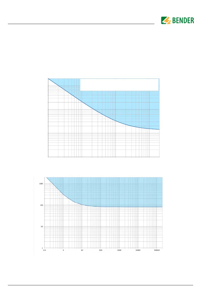
12.2 Diagrams of the leakage capacitance
The determination of the leakage capacitance depends on the size of the insulation resistance.
The following diagrams show the relationship.
Example:
Insulation resistance 50 kOhm => min. measurable leakage capacitance 35 µF
Insulation resistance 5 kOhm => min. measurable leakage capacitance 210 µF
Restriction for determining the leakage capacitance (iso1685DP; isoHV1685D)
Restriction for determining the leakage capacitance (isoLR1685DP)
1
10
100
1000
5005050,5
Capacitance [µF]
Fault resistance [k]
!"#$%!&'
!#$()"&'
Fault resistance [kΩ]
Leakage capacitance [μF]
Fault resistance [kΩ]
Leakage capacitance [μF]