Technical data
76
isoxx1685Dx-x25_D00272_07_M_XXEN/09.2022
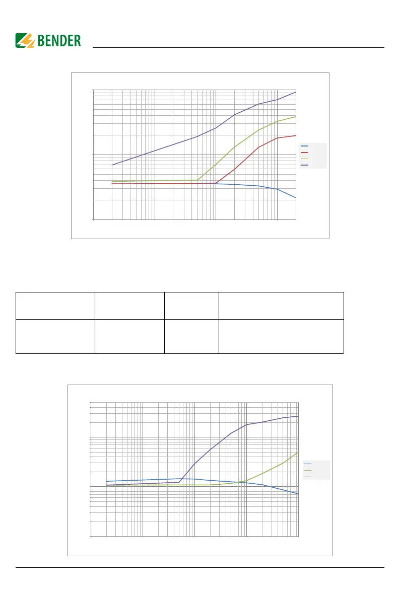
Diagram „High capacitance“
12.1.3 Inverter > 10 Hz
This profile is used for systems with dynamic frequency control by inverters in the range 10 to 460
Hz in order to optimise the measurement with respect to the measuring time and quality.
Diagram „Inverter < 10 Hz“
Power frequency
System leakage
capacitance
Measuring
voltage
Response value range
DC, 10…460 Hz 0…150 µF ±50 V iso1685DP: 200 …1 M
isoHV1685: 200 …1 M
isoLR1685DP: 20 …100 k
10
100
1000
0,1 1 10 100
Ce 1μF
Ce 50μF
Ce 100μF
Ce 500μF
Response value Ran [k]
an
[s]
(po: H )
1
10
100
0,1 1 10 100 1000
Ce 1μF
Ce 10μF
Ce 100μF
(po:)
Response value Ran [k]