2 Product Composition
3 / 64
2.2 System Composition
2.2.1 Panel Layout
2.2.1.1 Indicator Indication
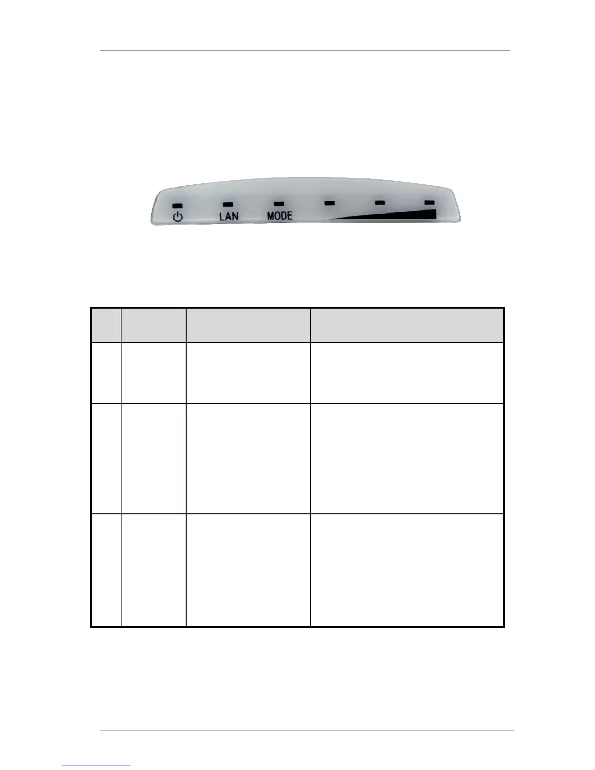
Figure 1 Indicator Panel
Table 2
No. Indicator Description Function
1
PWR
Power Indicator
(Yellow)
Long out-Power-off
Long bright-Power-on
2
LAN
Ethernet Indicator
Left port is primary
port
Right port is secondary
port
Always off
-AP mode
Always bright-Station、Repeater
mode
3
MODE Signal Lamp
Station mode-the last three lamps
stand for signal strength .
Repeater mode-the last three lamps
stand for signal strength.
AP mode-the last three lamps light.
 Loading...