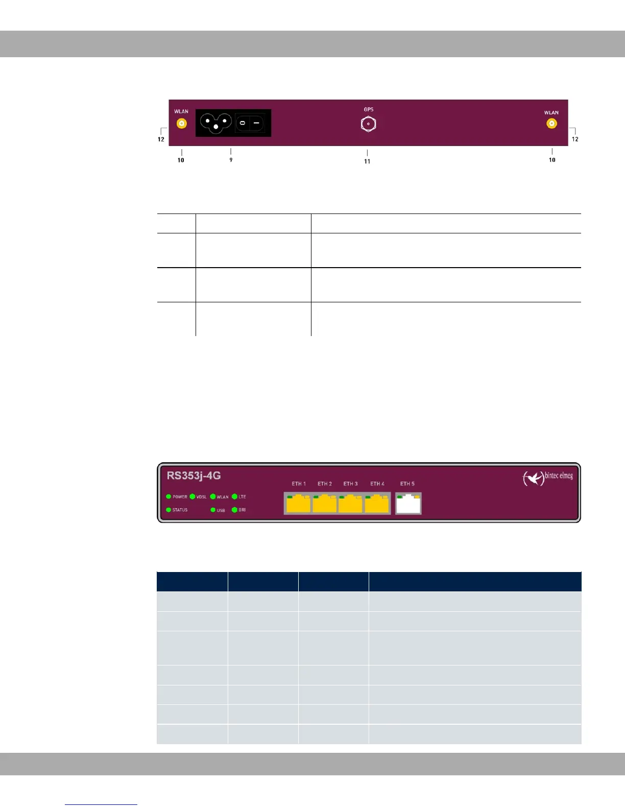
Fig. 4: bintec RS353j-4G rear panel
Rear pannel connections
9 POWER IEC C6 power connection and on/off switch
10 WLAN 1 / 2 Connections for the WLAN antenna (only bintec
RS353jw)
11 GPS Connection for the GPS antenna (only bintec
RS353j-4G)
12 LTE 1 - 2 Connections for the LTE/UMTS antenna (only bintec
RS353j-4G)
3.1.3 LEDs
The LEDs of your device provide information about specific activities and states of the
device.
The LEDs are arranged as follows:
Fig. 5: Arrangement of the LEDs
LED status display
LED Farbe Status Information
POWER green on Power supply is connected.
off No power supply.
STATUS green on After switching on: The device has started.
During operation: An error has occurred.
green flashing The device is active.
green off During operation: An error has occurred.
VDSL green on VDSL connection established.
green flashing Data traffic via VDSL send / receive.
3 Installation bintec elmeg GmbH
10 bintec RS Series