CB-110-410
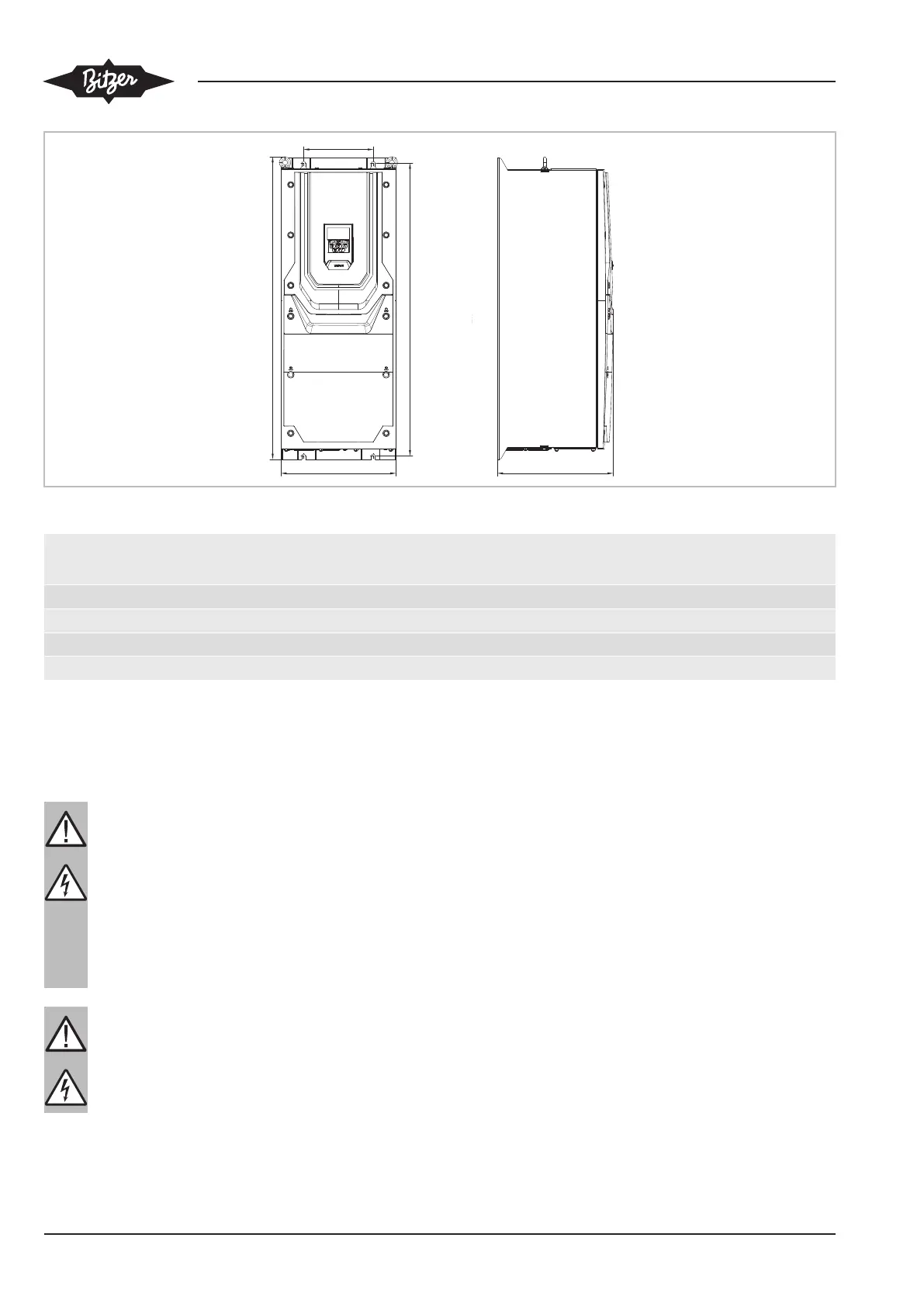
Fig.6: IP55
A
mm
B
mm
C
mm
D
mm
E
mm
FPW+61-4, FPW+72-4, FPW+90-4 540 235 270 520 175
FQW+110-4, FQW+150-4, FQW+180-4 865 330 330 840 200
FRW+202-4, FRW+240-4, FRW+302-4 1280 330 360 1255 200
FSW+370-4, FSW+480-4 1334 444 423 924 320
5 Electrical connection
Before performing any work on the electrical system:
DANGER
Life-threatening voltages inside the frequency
inverter housing!
Contact can lead to serious injuries or death.
Never open the FI housing in operation! Switch
off the main switch and secure it against being
switched on again.
Wait for at least 10 minutes until all capacitors
have been discharged!
Before switching on again, close the FI housing.
DANGER
As soon as the frequency inverter is energised,
the capacitors in the DC link are charged.
From this moment on, all electrical components
in the frequency inverter present risks!
The operation of the frequency inverter requires the fol-
lowing electrical connections:
• earth connection.
• power connections (voltage supply cable and motor
cable).
• control connections.
For the design of cable cross-sections, tightening
torques of earth and power connections and fuses see
chapter Cable cross-sections and tightening torques,
page 13. Fuses of type gG (IEC 60269) or UL fuses of
type J, T or CC, or thermal overload switches with cor-
responding characteristics must be used.
A fixed installation is required according to
IEC61800-5-1 with a suitable disconnecting device in-
stalled between the FI and the AC power source. The
disconnecting device must conform to the local safety
code / regulations (e.g. within Europe, EN60204-1,
Safety of machinery).
 Loading...