CB-110-4 19
0
f [Hz]
I [mA]
8 12 16 20
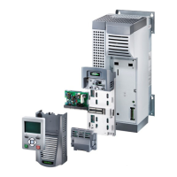
4 .. 20 mA
f [Hz]
0 2 4 6 8 10 12
U [V]
0 .. 10 V
f
max
f
min
f
max
f
min
4
f
max
user
compr.
user
compr.
user
f
max
user
Fig.10: "0..Max" control characteristic
5.8.3 Capacity control of the compressor as a
function of the evaporation pressure
To control the capacity of the compressor as a function
of the evaporation pressure requires the optional exten-
sion module for pressure control.
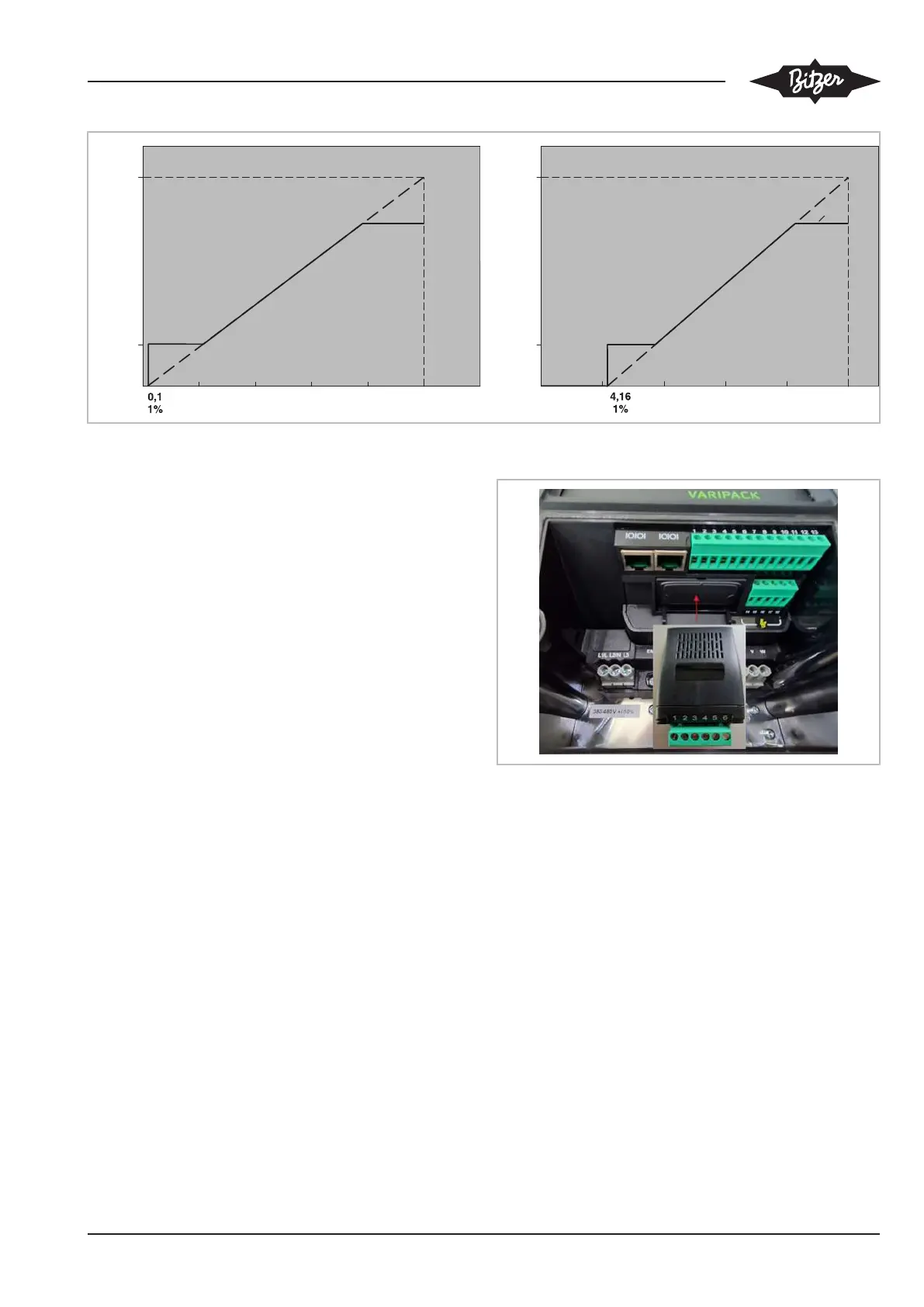
Installation of the extension module kit (part number
34797202):
• Remove cover of extension slot. Press the extension
module into the extension slot of the FI and tighten
the two screws with a T9 screwdriver.
• Pressure transmitter
– Install the pressure transmitter labelled
"TA-12,8SS" on the low pressure side.
– Install the pressure transmitter labelled
"TA-34,5SS" on the high pressure side.
– In the case of Schrader valves, install the pres-
sure transmitters without a copper gasket ring to
ensure safe opening (max. torque 15Nm).
Wiring of the extension module see chapter Schematic
wiring diagrams, page 28.
Fig.11: Extension module
 Loading...