CB-110-4 7
* External EMC filter for C2 EMC limit: Part number:
347 955 02, designation: FN 3359-250-28
** External EMC filter for C2 EMC limit: Part number:
347 955 03, designation: FN 3359-320-99
4 Mounting
All FI sizes:
• The frequency inverter must be mounted in a vertical
position only.
• Refer to technical data and ensure the chosen
mounting location is within the FI specification.
• The mounting location must be free from vibration.
IP20:
• IP20 units must be mounted in a switch cabinet.
IP55/66:
• Installation should be on a suitable flat, flame resist-
ant surface. Do not mount flammable material close
to the FI.
• Do not mount the FI in any area with excessive hu-
midity, corrosive airborne chemicals or potentially
dangerous dust particles.
• Do not mount close to high heat sources.
• The FI must not be mounted in direct sunlight. If ne-
cessary, install a suitable shade cover.
• Do not restrict the flow of air through the FI heatsink.
The FI generates heat which must be naturally al-
lowed to dissipate. Correct air clearance around the
FI must be observed.
4.1 Transport and storage
NOTICE
Risk of damage to the frequency inverter!
Do not lift or put down the frequency inverter on
the connections.
Place it on clean, flat and dry surfaces only.
Storage in well-ventilated places only and pro-
tected from high temperatures, humidity, dust
and metal particles!
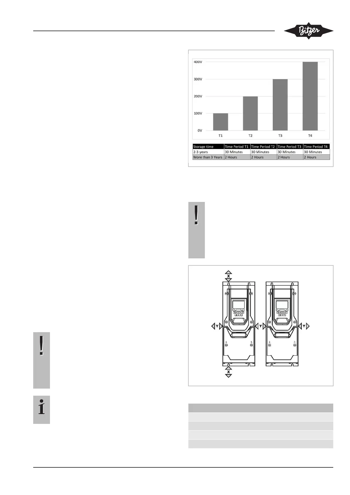
Information
If the FI (FQ. and FR. series) has been in stor-
age for a period longer than 2 years, the DC link
capacitors must be reformed.
Fig.2: Reformation
4.2 Ventilation
NOTICE
The frequency inverters give off heat during op-
eration. Typical drive heat losses are 2% of op-
erating load conditions.
Insufficient or blocked air circulation and air sup-
ply at the heat sink of the frequency inverter can
lead to failure due to overheating!
Observe the minimum clearances for ventilation!
Fig.3: Minimum ventilation clearances
FI size X Y
FMU, FNU 100 mm 10 mm
FOU .. FQU 200 mm 25 mm
F.Y .. F.W 200 mm 10 mm
FS. 400 mm 10 mm
 Loading...