30 MT55 Operation & Maintenance Manual
HYDRAULIC CONTROLS (CONT’D)
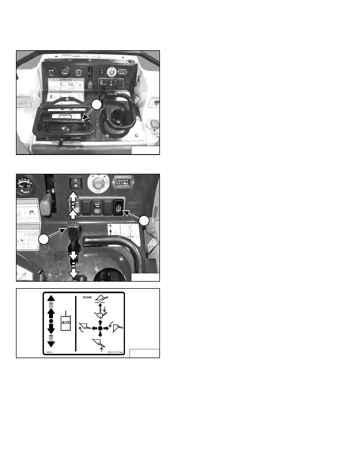
FRONT Auxiliary Hydraulics (CONTINUOUS FLOW)
Figure 20
Figure 21
Variable Flow:
Push the Auxiliary Hydraulic Control Lever (Item 1)
[Figure 20] forward for auxiliary hydraulic oil flow to the
front male coupler (Item 2) [Figure 21]. Hydraulic oil flow
increases to the coupler as the lever is pushed forward.
Pull the Auxiliary Hydraulic Control Lever (Item 1)
[Figure 21] backward for auxiliary hydraulic oil flow to the
front female coupler (Item 1) [Figure 22]. Hydraulic oil
flow increases to the coupler as the lever is pushed
backward.
Continuous Flow:
While holding the Continuous Flow Shutoff Lever (Item 1)
[Figure 20] down, push the Auxiliary Hydraulic Control
Lever (Item 1) [Figure 21] all the way forward or all the
way backward until it locks (detent position) for
continuous auxiliary hydraulic oil flow for an attachment
such as a tiller or trencher.
If the Continuous Flow Shutoff Lever (Item 1) [Figure 20]
is released while in continuous flow, the Auxiliary
Hydraulic Control Lever (Item 1) [Figure 21] will return to
NEUTRAL after one to three seconds and the auxiliary
hydraulic oil flow will stop.
To resume the continuous flow operation, make sure the
Auxiliary Hydraulic Control Lever (Item 1) [Figure 21] is
in NEUTRAL and press down on the Continuous Flow
Shutoff Lever (Item 1) [Figure 20]. Move the Auxiliary
Hydraulic Control Lever (Item 1) [Figure 21] all the way
forward or all the way backward until it locks (detent
position).
NOTE: The Continuous Flow Shutoff Lever (Item 1)
[Figure 20] must be in the UP position and the
Auxiliary Hydraulic Control Lever (Item 1)
[Figure 21] must be in NEUTRAL to start the
engine.
NOTE: The Continuous Flow Shutoff Lever (Item 1)
[Figure 20] must return to the UP position
when it is released.
Auxiliary Hydraulic Mode Switch:
For operation with the backhoe attachment, the Auxiliary
Hydraulic Mode Switch (Item 2) [Figure 21] must be
installed. The auxiliary hydraulic continuous flow
functions normally when the switch is in the "A" position.
Place the switch in the "B" position for backhoe
operation. Move the Auxiliary Hydraulic Control Lever all
the way backward until it locks (detent position). Auxiliary
hydraulic oil will flow to the front female coupler.
If the Continuous Flow Shutoff Lever (Item 1) [Figure 20]
is pressed while the Auxiliary Hydraulic Mode Switch
(Item 2) [Figure 21] is in the "B" position, the Auxiliary
Hydraulic Control Lever (Item 1) [Figure 21] will return to
NEUTRAL and the auxiliary hydraulic oil flow will stop.
Move the switch to "A" position when you are done with
the backhoe operation.
Dealer Copy -- Not for Resale