66 MT55 Operation & Maintenance Manual
AUXILIARY HYDRAULIC CONTROL SYSTEM
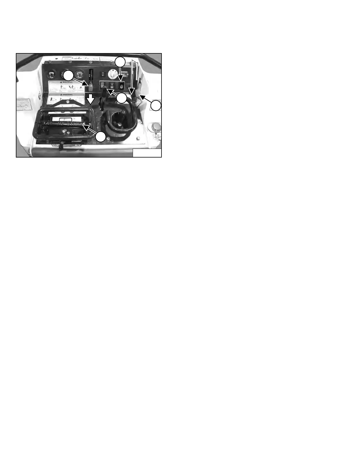
Inspecting The Continuous Flow Shutoff Lever
Figure 73
1. Stop the engine and engage the parking brake (Item
1) [Figure 73].
2. Make sure the area around the machine is clear of
bystanders.
3. Set the engine speed to slow (Item 2) [Figure 73].
4. Turn the key to the ON position but do not start the
engine.
5. Move the Auxiliary Hydraulic Mode Switch (Item 5)
[Figure 73] to the “A” position (if equipped).
6. Depress the Continuous Flow Shutoff Lever (Item 3)
[Figure 73] so the lever is in the DOWN position.
7. Move the Auxiliary Hydraulic Control Lever (Item 4)
[Figure 73] fully forward into the locked (detent)
position.
8. Release the Continuous Flow Shutoff Lever (Item 3)
[Figure 73]. The lever must return to the UP position.
9. The Auxiliary Hydraulic Control Lever (Item 4)
[Figure 73] must return to the NEUTRAL position in
approximately one to three seconds.
10. Repeat the procedure with the Auxiliary Hydraulic
Control Lever (Item 4) [Figure 73] fully backward into
the locked (detent) position.
NOTE: Contact your dealer for service if the
Continuous Flow Shutoff Lever does not
function properly.
Inspecting The Auxiliary Hydraulic Mode Switch (If
Equipped)
Perform the “Inspecting The Continuous Flow Shutoff
Lever” procedure with the Auxiliary Hydraulic Mode
Switch (Item 5) [Figure 73] in the “A” position”.
Perform the following procedure with the Auxiliary
Hydraulic Mode Switch (Item 5) [Figure 73] in the “B”
position.
1. Stop the engine and engage the parking brake (Item
1) [Figure 73].
2. Make sure the area around the machine is clear of
bystanders.
3. Set the engine speed to slow (Item 2) [Figure 73].
4. Turn the key to the ON position but do not start the
engine.
5. Move the Auxiliary Hydraulic Mode Switch (Item 5)
[Figure 73] to the “B” position.
6. Move the Auxiliary Hydraulic Control Lever (Item 4)
[Figure 73] fully forward into the locked (detent)
position.
7. Depress the Continuous Flow Shutoff Lever (Item 3)
[Figure 73] so the lever is in the DOWN position.
8. The Auxiliary Hydraulic Control Lever (Item 4)
[Figure 73] must return to the NEUTRAL position.
9. Repeat the procedure with the Auxiliary Hydraulic
Control Lever (Item 4) [Figure 73] fully backward into
the locked (detent) position.
10. Move the Auxiliary Hydraulic Mode Switch (Item 5)
[Figure 73] back to the "A" position.
NOTE: Contact your Bobcat dealer for service if the
Auxiliary Hydraulic Mode Switch does not
function properly.
Dealer Copy -- Not for Resale