787 Flight Crew Operations Manual
DO NOT USE FOR FLIGHT
Engines, APU -
Engine System Description
Copyright © The Boeing Company. See title page for details.
D615Z003-TBC 7.20.15
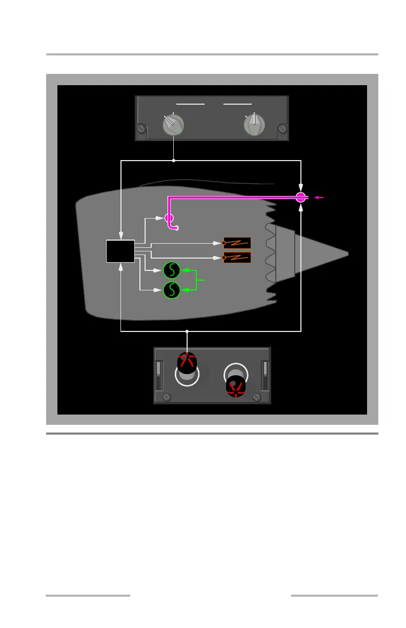
Engine Start and Ignition System Schematic
Engine Fuel System
[Option – GE engines]
Fuel is supplied by pumps located in the fuel tanks. The fuel flows through a spar
valve located in the main tank. It then passes through the first stage engine fuel
pump where additional pressure is added. It flows through a fuel/oil heat
exchanger where it is preheated. The fuel then passes through the second stage
engine fuel pump where additional pressure is added. A fuel filter removes
contaminants before the fuel reaches the fuel metering unit. The fuel metering unit
adjusts fuel flow to meet thrust requirements. The fuel then flows through the
engine fuel valve into the engine.
Fuel
Spar
Fuel Valve
Starter/Generators
Ignitors
Electrical Power
Engine
Fuel Valve
L FUEL CONTROL R
RUN
CUTOFF
L
NORM
START
RSTART
START
NORM
EEC
February 15, 2010