787 Flight Crew Operations Manual
DO NOT USE FOR FLIGHT
Engines, APU -
Engine System Description
Copyright © The Boeing Company. See title page for details.
7.20.20 D615Z003-TBC
[Option – RR engines]
Thrust Reverser System
Each engine has a hydraulically actuated fan air thrust reverser. Reverse thrust is
available only on the ground.
The reverse thrust levers can be raised only when the forward thrust levers are in
the idle position. When the reverse thrust levers are raised, the EEC opens the
reverser isolation valve. The EEC inhibits reverser isolation valve actuation and
reverser deployment unless the airplane is on the ground with the engine running.
The EECs also control thrust limits during reverser operation.
There is a physical interlock located in the aisle stand to prevent movement of the
reverse thrust lever beyond the reverse idle position until the cowl is partially
deployed. The interlock provides tactile feedback to the pilot that the thrust
reverser is or is not deployed.
When the reverse thrust levers are pulled aft to the interlock position:
• the autothrottle disengages
• the auto speedbrakes deploy
When the reverser system is activated:
• the reverser translating sleeves hydraulically move aft
• the fan flow blocker doors rotate into place to direct fan air through
stationary cascade guide vanes
[Option – GE engines]
• the reverser indication REV is displayed in amber above each digital N1
indication (REV is displayed in amber when the reverser is in transit)
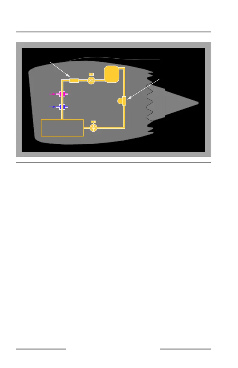
Air/Oil
Heat Exchanger
Air
Fuel/Oil
Heat Exchanger
Fuel
High Pressure
Oil Filter
Scavenge
Oil Filter
Gearbox
Main Bearings
Accessory Drives
Oil
Pump
Oil
Tank
B
Scavenge
Pump
February 15, 2010