S P00 D00 159 2019-03-01| Robert Bosch GmbH
Product description | ACS 752 | 41 en
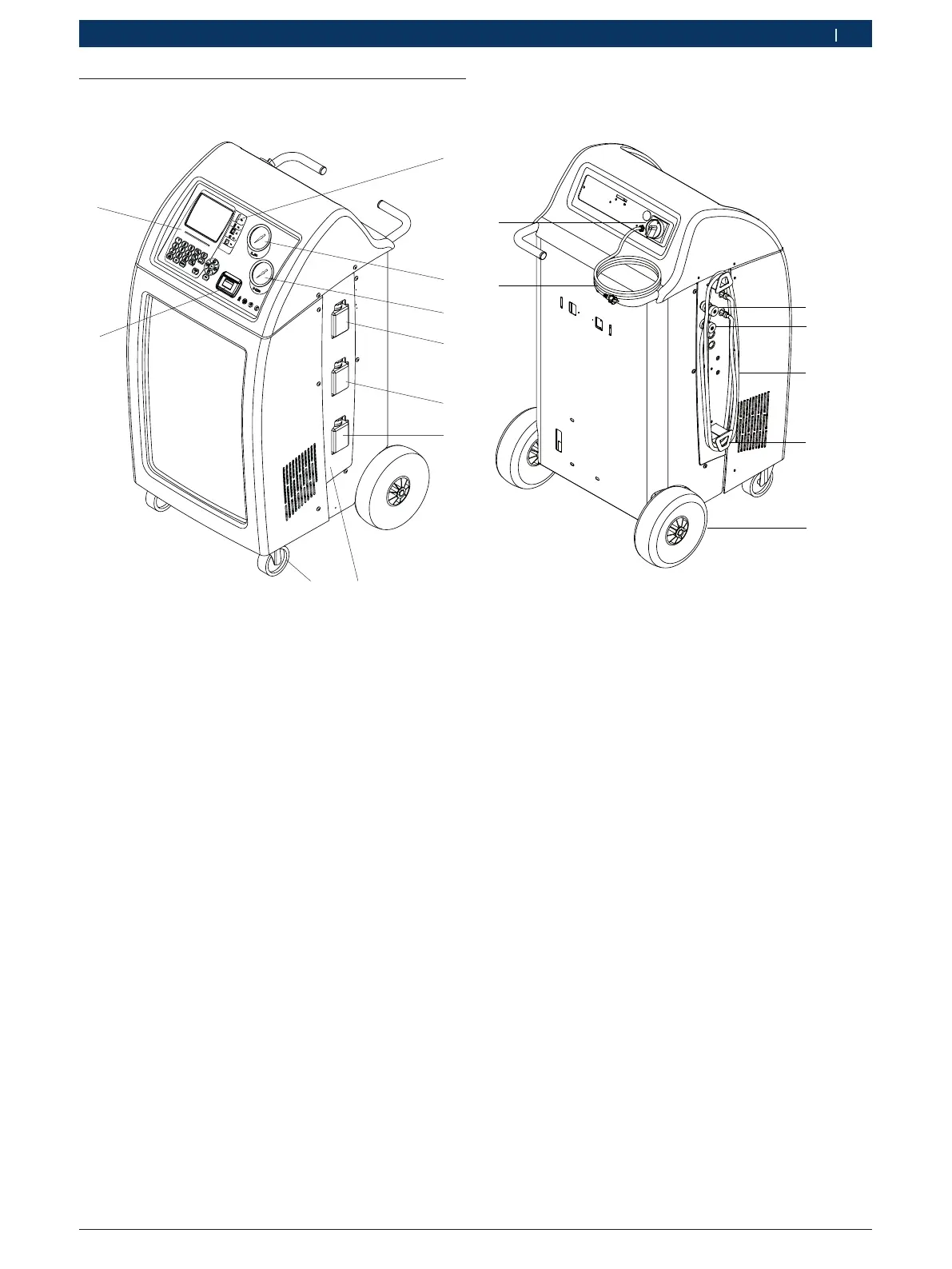
4.4 Description of unit
4.4.1 Front view
1
2
4
6
5
3
7
8
Fig. 1: Front view
1 Printer
2 Display and control panel
3 Connecting ports and slots
4 Gauge low pressure (LP)
5 Gauge high pressure (HP)
6 Fresh oil bottle PAG
7 UV dye bottle or Fresh oil bottle POE
1)
8 Used oil bottle
9 Cover (fixed by magnets)
10 Front wheels with locking brake
1)
See chapter 7.5
i The high (5) and low pressure (4) gages show the cur-
rent pressure during the air conditioning service on
the vehicle.
4.4.2 Rear view
1
5
4
3
2
6
Fig. 2: Rear
1 Service quick-release coupling and hose flushing port (LP)
2 Service quick-release coupling and hose flushing port (HP)
3 Service hoses (2,5 m)
4 Service hoses mount
5 Rear wheels
6 Power cord (socket)
7 Master switch
 Loading...


