POINT 1 COM POINT 2 POINT 3 COM POINT 4 POINT 5 COM POINT 6 POINT 7 COM POINT 8
ZONEX TMPR
SDIx SDI2
MODULE RELEASE
MOD-2
MOD-1
USB POWER
STATUS
RESETZONEX
TMPR
SDI2
PWR+/R
A/Y
B/G
COM/B
PWR+/R
A/Y
B/G
COM/B
B
A
S
E
L
I
N
K
T
ETHERNET
USB
11
Point 5
Point 6
Point 3 Point 4
Point 1
Point 2
Point 7
Point 8
EARTH GROUND
ON-BOARD POINTS
COMMON
BATTERY (
-
)
+ AUX POWER
BATTERY ( + )
CLASS 2
16.5 VAC 40 VA 60 Hz
TRANSFORMER
10
9
8
7
6
5
4
3
2
1
1 k End-of-line-Resistors Required (P/N 15093130-004), Max Loop Current: 5 mA
13 14
16
17
19
20
22
12
15
18
21
24
25
26
28
29
30
23
27
Quick Flash:
Low
BATTERY STATUS
Slow Flash:
Charging
Off: Normal
Minimum system requirements for Classification in accordance with ANSI/SIA
CP-01-2010. UL Listed and Classified control unit Model B9512G and B8512G.
UL Listed and Classified keypad Model B942, B930, B925F, B926F, B921C,
B920, B915, D1255RB, D1256RB and D1257RB. UL Listed Local Bell.
WARNING!
Multi-Battery
installation requires
Model D122 or D122L
Dual Battery Harness.
Improper installation
can be a fire hazard
.
WARNING!
Incorrect wiring will
damage this
equipment.
Devices powered by
any output must be
supervised.
The equipment should be installed in accordance with the NFPA 70 (National Electrical
Code) and NFPA 72 (National Fire Alarm Code).
Depending on the application, the installation may need to be in accordance with one or
more of the following UL standards: UL681, UL1076, UL1641 and C22.1, CEC, Part 1.
Use of a D185 is not suitable for remote station protected premises service where separate
transmissions circuits are required for fire, supervisory (when applicable) and trouble
signals.
SDIx
Refer to the system wiring diagrams in the B9512G/B8512G
ULLD and to the D125B Installation Instructions for compatible
smoke detectors. 2-wire Compatible Identifier “A”. Printed
information describing proper installation, operation, testing,
maintenance, repair service and response to an alarm is to be
provided with this equipment.
POWER SUPPLY REQUIREMENTS
The Power Supply provides a maximum of 1.4 Amps for the Control Panel and all Accessory Devices. For System Loading,
refer to the B9512G/B8512G UL Listing Document, ULLD. Auxiliary powered devices: 11.8 to 12.5 VDC
The system is intended to be checked by a Qualified Technician at least every 3 years. The types of initiating circuits the control
panel has been approved for are A, M, WF, SS. The types of signaling the control panel has been approved for are DAC, OT, NC,
RevPol.
Battery: Replace every 3 to
5 years with one or two
Model D126 or D1218 12V
Lead Acid Batteries.
The B9512G/B8512G Control Panel is UL Listed For CS, RS, L, AUX, Prop and Res Fire and Res, Prop,
Cent. Stat, Local, and PS Con. Merc. Burg, MSV, BSV, Holdup, suitable as a dual line trans. sys.
Signaling means: DAC, Cell or IP
WARNING!
To prevent risk of shock,
disconnect AC power and
communication lines before
servicing.
All external connections except Terminal 5 (BATTERY(+) are inherently power limited.
Requirements for battery standby time might reduce allowable output.
On:
Missing
Low 12.1 VDC
Load Shed 10.2 VDC
OUTPUT
B (2)
OUTPUT
A (1)
OUTPUT
C (3)
Do not connect
to a receptacle
controlled by
a switch.
Voltage Ranges: Open 3.7 - 5.0 VDC,
Short 0.0 - 1.3 VDC, Normal 2.0 - 3.0 VDC
WARNING!
Owner Instructions (P/N F.01U.307.371): Not to
be removed by anyone except occupant.
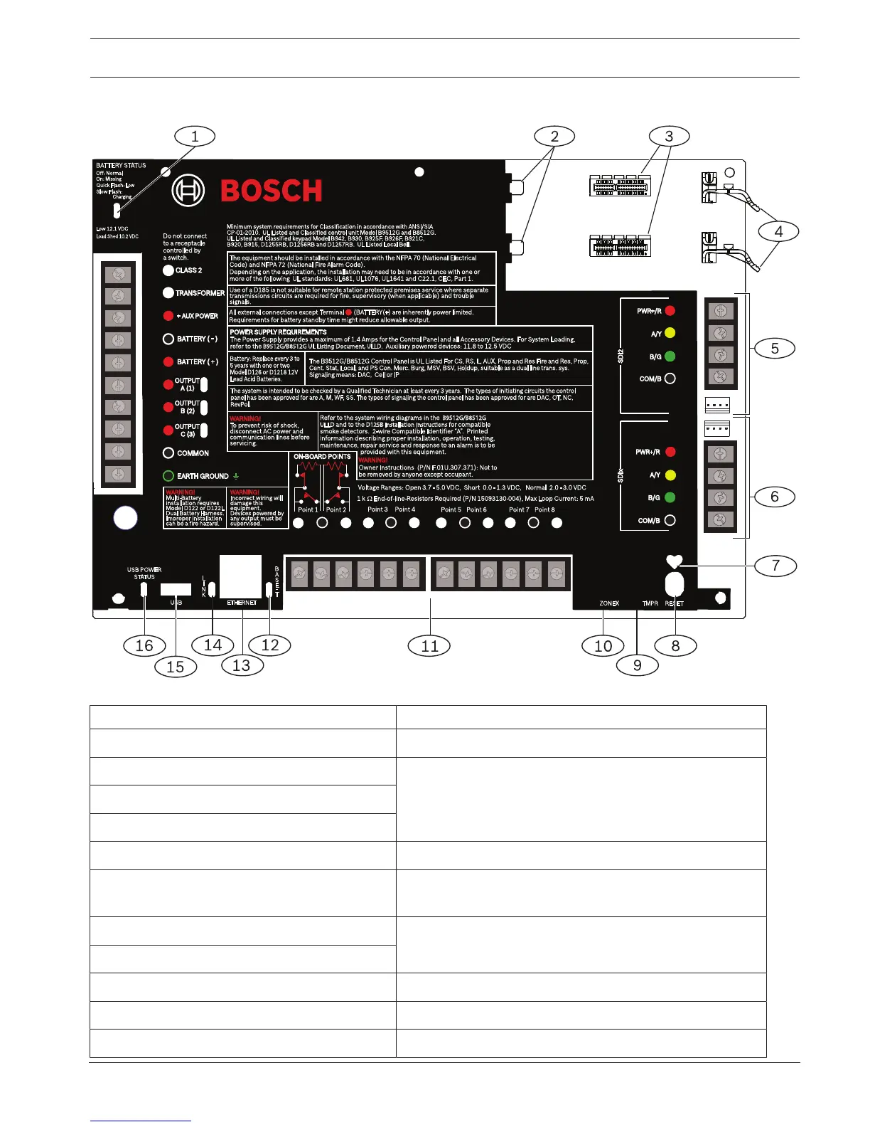
Figure17.18: Control panel board overview
Callout ᅳ Description For more information, refer to:
1 ᅳ BATTERY STATUS LED Battery discharge and recharge schedule, page 40
2 ᅳ Holes to stabilize plug-in modules Installation and module wiring (B430), page 44 or
Installation and module wiring (B44x), page 50
3 ᅳ Plug-in module connectors
4 ᅳ Plug-in module retention clips
5 ᅳ SDI2 wiring SDI2 devices general system wiring, page 98
6 ᅳ SDIx wiring (use as SDI or SDI2) SDI2 devices general system wiring, page 98 or SDI and
ZONEX wiring, page 96
7 ᅳ Heartbeat LED (blue) Installer keypads and SERVICE MODE, page 115
8 ᅳ RESET button
9 ᅳ Tamper switch connector location Install the enclosure, page 31
10 ᅳ Zonex module connector location SDI and ZONEX wiring, page 96
11 ᅳ Sensor loop terminals for points 1 to 8 On-board points, page 72

 Loading...


