DP-EA4 Peripheral Bus Station Module
9–4
1070 072 145-102 (01.07) GB
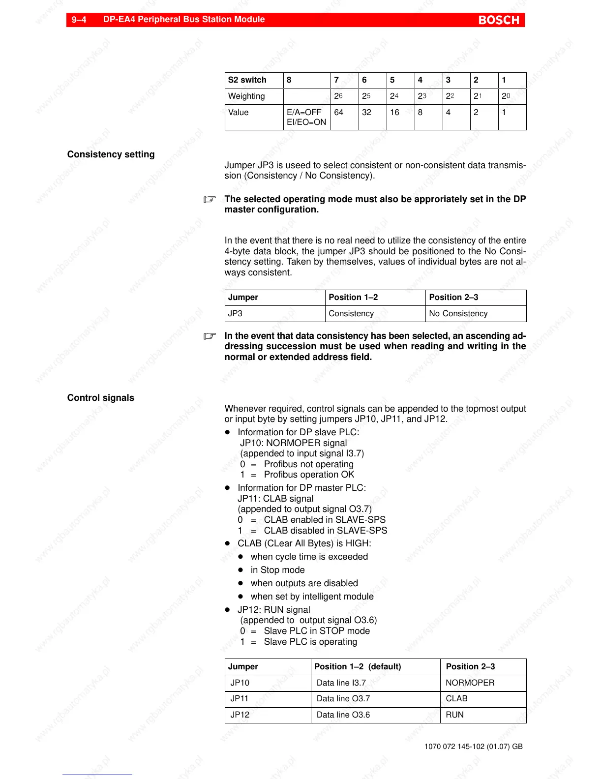
S2 switch 8 7 6 5 4 3 2 1
Weighting 2^ 2% 2$ 2# 2@ 2! 2)
Value E/A=OFF
EI/EO=ON
64 32 16 8 4 2 1
Consistency setting
Jumper JP3 is useed to select consistent or non-consistent data transmis-
sion (Consistency / No Consistency).
. The selected operating mode must also be approriately set in the DP
master configuration.
In the event that there is no real need to utilize the consistency of the entire
4-byte data block, the jumper JP3 should be positioned to the No Consi-
stency setting. Taken by themselves, values of individual bytes are not al-
ways consistent.
Jumper Position 1–2 Position 2–3
JP3 Consistency No Consistency
. In the event that data consistency has been selected, an ascending ad-
dressing succession must be used when reading and writing in the
normal or extended address field.
Control signals
Whenever required, control signals can be appended to the topmost output
or input byte by setting jumpers JP10, JP11, and JP12.
D Information for DP slave PLC:
JP10: NORMOPER signal
(appended to input signal I3.7)
0 = Profibus not operating
1 = Profibus operation OK
D Information for DP master PLC:
JP11: CLAB signal
(appended to output signal O3.7)
0 = CLAB enabled in SLAVE-SPS
1 = CLAB disabled in SLAVE-SPS
D CLAB (CLear All Bytes) is HIGH:
D when cycle time is exceeded
D in Stop mode
D when outputs are disabled
D when set by intelligent module
D JP12: RUN signal
(appended to output signal O3.6)
0 = Slave PLC in STOP mode
1 = Slave PLC is operating
Jumper Position 1–2 (default) Position 2–3
JP10 Data line I3.7 NORMOPER
JP11 Data line O3.7 CLAB
JP12 Data line O3.6 RUN