RM2-DP12 Module
16–3
1070 072 145-102 (01.07) GB
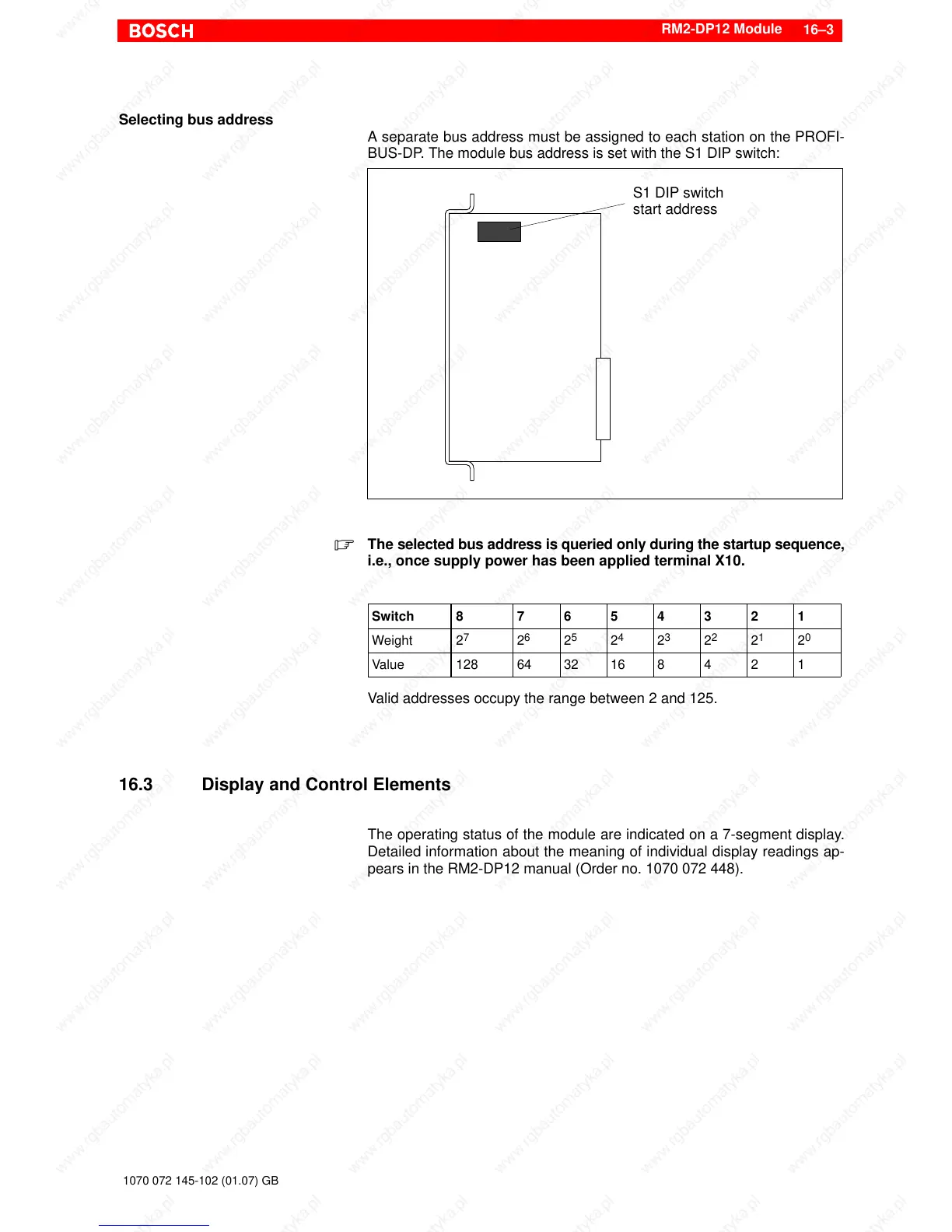
Selecting bus address
A separate bus address must be assigned to each station on the PROFI-
BUS-DP. The module bus address is set with the S1 DIP switch:
S1 DIP switch
start address
. The selected bus address is queried only during the startup sequence,
i.e., once supply power has been applied terminal X10.
Switch 8 7 6 5 4 3 2 1
Weight 2
7
2
6
2
5
2
4
2
3
2
2
2
1
2
0
Value 128 64 32 16 8 4 2 1
Valid addresses occupy the range between 2 and 125.
16.3 Display and Control Elements
The operating status of the module are indicated on a 7-segment display.
Detailed information about the meaning of individual display readings ap-
pears in the RM2-DP12 manual (Order no. 1070 072 448).
 Loading...


