Digital Input/Output Modules
8–1
1070 072 145-102 (01.07) GB
8 Digital Input/Output Modules
8.1 Functions and Features
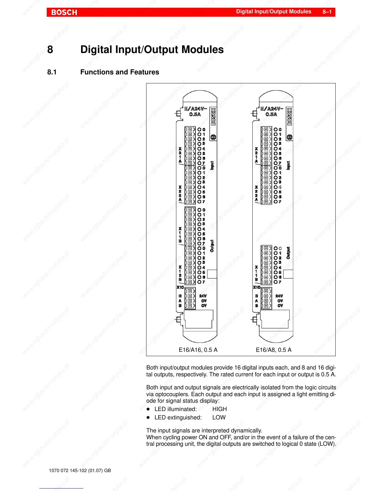
E16/A16, 0.5 A E16/A8, 0.5 A
Both input/output modules provide 16 digital inputs each, and 8 and 16 digi-
tal outputs, respectively. The rated current for each input or output is 0.5 A.
Both input and output signals are electrically isolated from the logic circuits
via optocouplers. Each output and each input is assigned a light emitting di-
ode for signal status display:
D LED illuminated: HIGH
D LED extinguished: LOW
The input signals are interpreted dynamically.
When cycling power ON and OFF, and/or in the event of a failure of the cen-
tral processing unit, the digital outputs are switched to logical 0 state (LOW).