Installation
17–9
1070 072 145-102 (01.07) GB
17.2.10 Earthing
Functional earthing
The GG3 and GG3-K module racks of the CL200 must be mounted on a me-
tallic, earthed support, such as the rear panel of a control cabinet, for exam-
ple.
Functional earthing is required to provide optimum interference protection.
The functional earthing connection must comprise the shortest possible ca-
ble or consist of a grounding strap, the latter being the preferred solution.
Guidance value: Length: max. 1 m
Cross-section: 6 mm
2
Equipotential bonding
Equipotential bonding must be established between system components
and power supply, as per DIN VDE 0100, Part 540.
Protective Earth (PE)
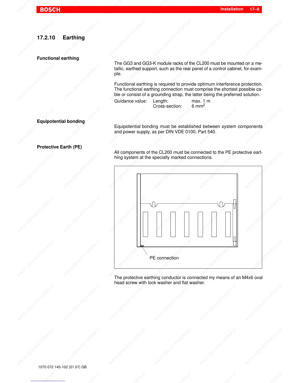
All components of the CL200 must be connected to the PE protective eart-
hing system at the specially marked connections.
PE connection
The protective earthing conductor is connected my means of an M4x6 oval
head screw with lock washer and flat washer.