DP-EA4 Peripheral Bus Station Module
9–3
1070 072 145-102 (01.07) GB
9.2 Display and Control Elements, Connections and Settings
Diagnostics
The “Stop” LED indicates the operating status of the DP ring.
D LED extinguished: Normal operating status
D LED illuminates: Fault in DP operation
Pressing the RESET button triggers a hardware RESET. The module will
subsequently attempt to reestablish a new DP connection.
PROFIBUS-DP connection
The PROFIBUS-DP connection uses a female DB-9 connector.
DP addressing
The PROFIBUS-DP slave address is selected on the 8-segment S1 DIP
switch.
S1 switch 8 7 6 5 4 3 2 1
Weighting 2& 2^ 2% 2$ 2# 2@ 2! 2)
Value 128 64 32 16 8 4 2 1
The major device specification file (GSD file) for this module must be selec-
ted in the WinDP configuration software for the PROFIBUS-DP.
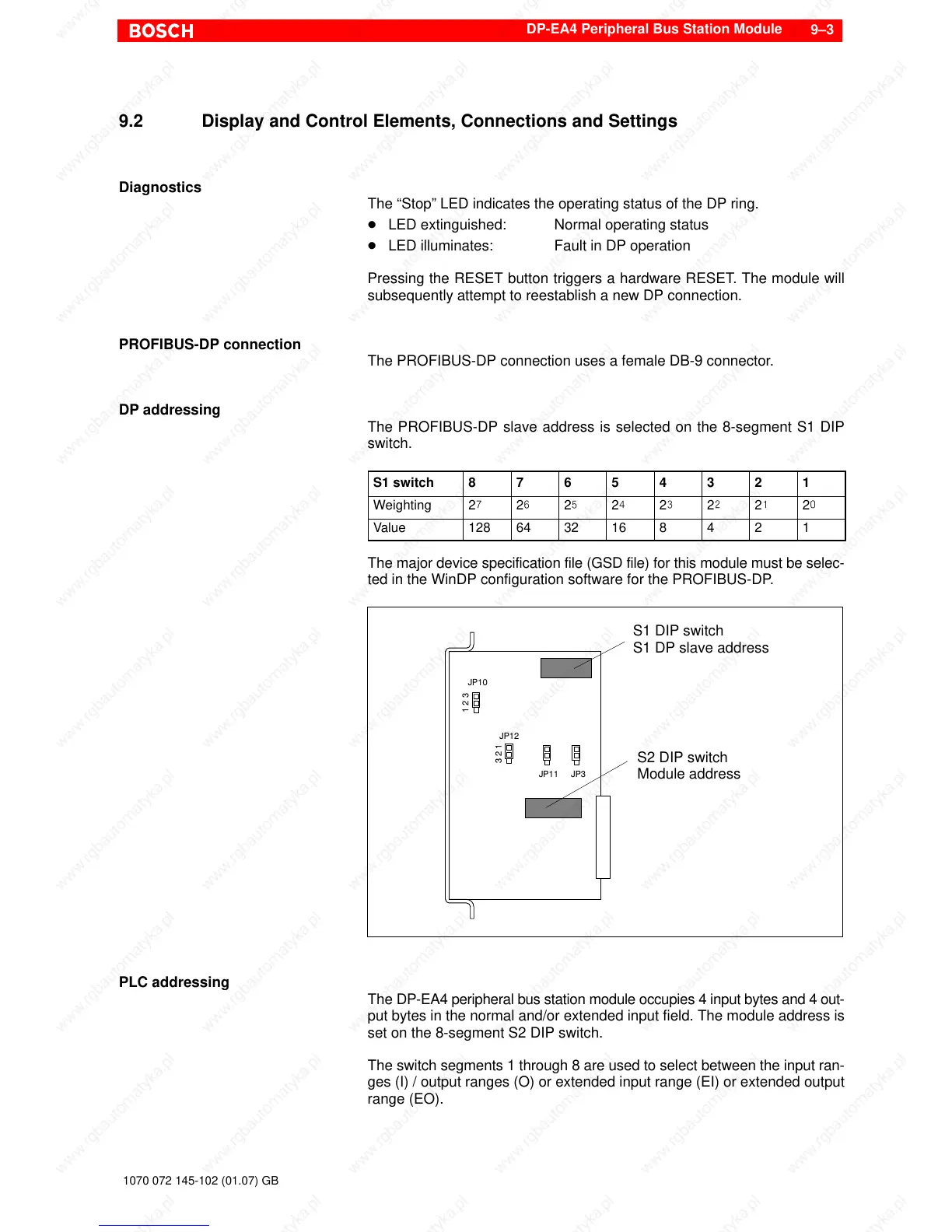
S1 DIP switch
S1 DP slave address
S2 DIP switch
Module address
1 2 3
JP10
3 2 1
JP12
JP11 JP3
PLC addressing
The DP-EA4 peripheral bus station module occupies 4 input bytes and 4 out-
put bytes in the normal and/or extended input field. The module address is
set on the 8-segment S2 DIP switch.
The switch segments 1 through 8 are used to select between the input ran-
ges (I) / output ranges (O) or extended input range (EI) or extended output
range (EO).