Digital Input/Output Modules
8–8
1070 072 145-102 (01.07) GB
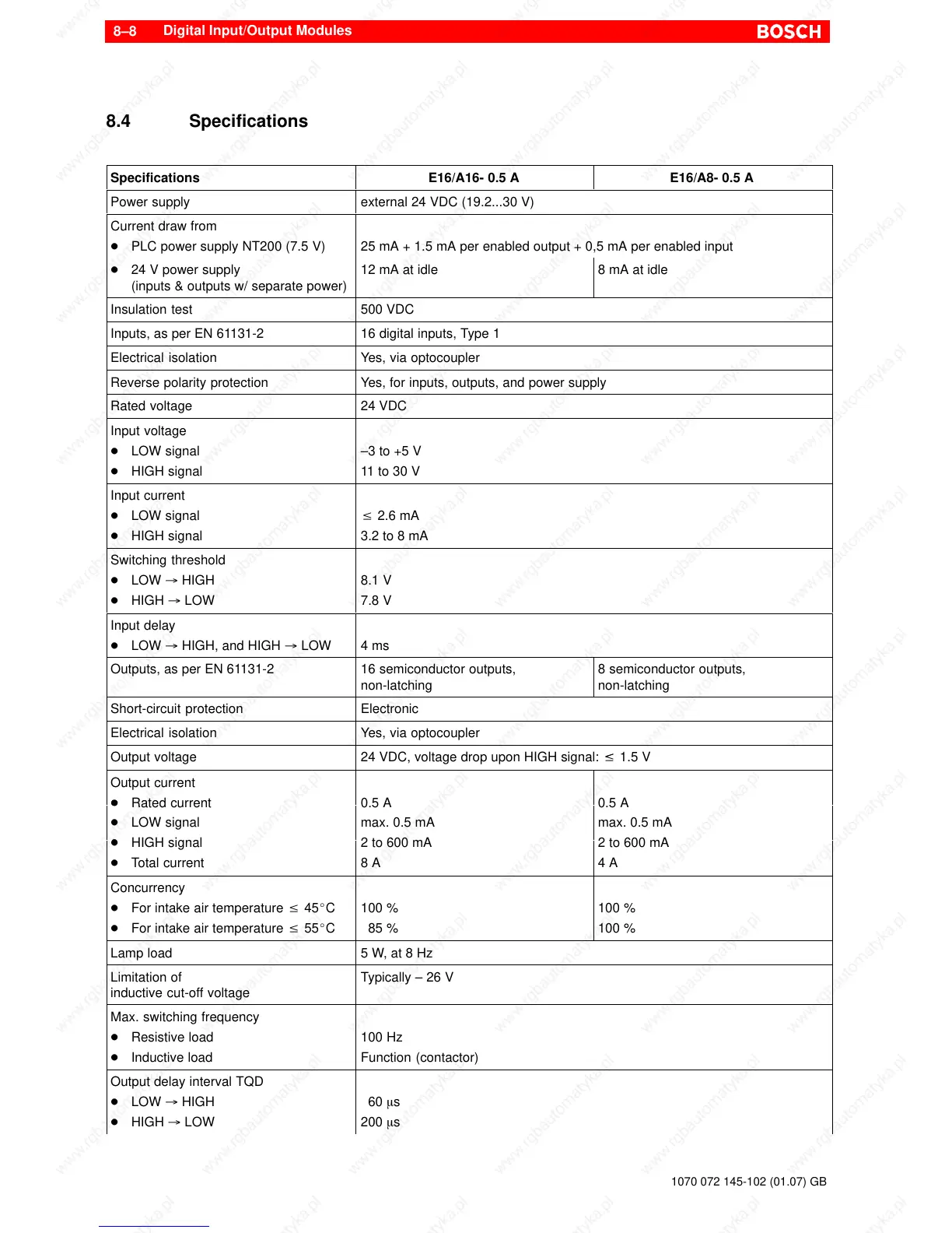
8.4 Specifications
Specifications E16/A16- 0.5 A E16/A8- 0.5 A
Power supply external 24 VDC (19.2...30 V)
Current draw from
D PLC power supply NT200 (7.5 V)
25 mA + 1.5 mA per enabled output + 0,5 mA per enabled input
D 24 V power supply
(inputs & outputs w/ separate power)
12 mA at idle 8 mA at idle
Insulation test 500 VDC
Inputs, as per EN 61131-2 16 digital inputs, Type 1
Electrical isolation Yes, via optocoupler
Reverse polarity protection Yes, for inputs, outputs, and power supply
Rated voltage 24 VDC
Input voltage
D LOW signal
D HIGH signal
–3 to +5 V
11 to 30 V
Input current
D LOW signal
D HIGH signal
v 2.6 mA
3.2 to 8 mA
Switching threshold
D LOW ³ HIGH
D HIGH ³ LOW
8.1 V
7.8 V
Input delay
D LOW ³ HIGH, and HIGH ³ LOW
4 ms
Outputs, as per EN 61131-2 16 semiconductor outputs,
non-latching
8 semiconductor outputs,
non-latching
Short-circuit protection Electronic
Electrical isolation Yes, via optocoupler
0.5 A
max. 0.5 mA
0.5 A
max. 0.5 mA
D HIGH signal
D Total current
2 to 600 mA
8 A
2 to 600 mA
4 A
Concurrency
D For intake air temperature v 45_C
D For intake air temperature v 55_C
100 %
85 %
100 %
100 %
Lamp load 5 W, at 8 Hz
Limitation of
inductive cut-off voltage
Typically – 26 V
Max. switching frequency
D Resistive load
D Inductive load
100 Hz
Function (contactor)
Output delay interval TQD
D LOW ³ HIGH
D HIGH ³ LOW
60 ms
200 ms