E 24 V– Digital Input Modules
6–4
1070 072 145-102 (01.07) GB
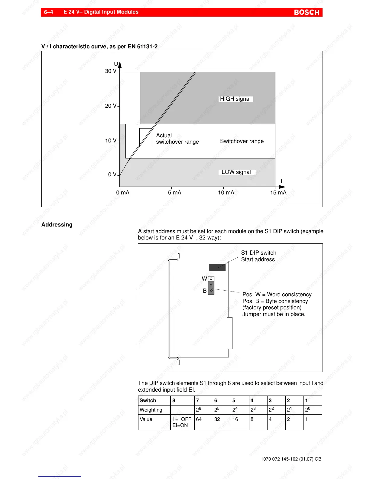
V / I characteristic curve, as per EN 61131-2
30 V
20 V
0 V
10 V
0 mA 5 mA 10 mA 15 mA
HIGH signal
LOW signal
Switchover range
Actual
switchover range
U
I
Addressing
A start address must be set for each module on the S1 DIP switch (example
below is for an E 24 V–, 32-way):
S1 DIP switch
Start address
Pos. W = Word consistency
Pos. B = Byte consistency
(factory preset position)
Jumper must be in place.
W
B
The DIP switch elements S1 through 8 are used to select between input I and
extended input field EI.
Switch 8 7 6 5 4 3 2 1
Weighting 2
6
2
5
2
4
2
3
2
2
2
1
2
0
Value I = OFF
EI=ON
64 32 16 8 4 2 1