Digital Output Modules
7–3
1070 072 145-102 (01.07) GB
F2
F1
Power circuit A
Power circuit B
L Using a suitable tool, extract fuse F1 or F2 from socket, then insert new 3.0 A
FF fuse. The fuse is supplied complete with fuse holder.
L Insert module in module rack, and push home firmly.
L Reconnect push-lock terminals.
L Switch ON power supply.
Addressing
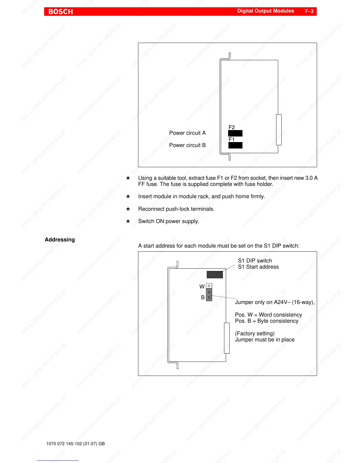
A start address for each module must be set on the S1 DIP switch:
S1 DIP switch
S1 Start address
Jumper only on A24V– (16-way),
Pos. W = Word consistency
Pos. B = Byte consistency
(Factory setting)
Jumper must be in place
W
B