Digital Output Modules
7–11
1070 072 145-102 (01.07) GB
Specifications AR/2 AA 24 V– / 2 AA 24 V– / 0.5 A
(16-way)
A 24 V– / 0.5 A
(32-way)
Push-lock terminals
Max. cable cross-section
Max. terminal current
1.5 mm@
8 A
Cable length max. 200 m,
unscreened,
max. 300 m,
screened
max. 100 m, unscreened
Width 1 slot
Weight 280 g 210 g 200 g 290 g
Terminal form factor 3.5 5.08
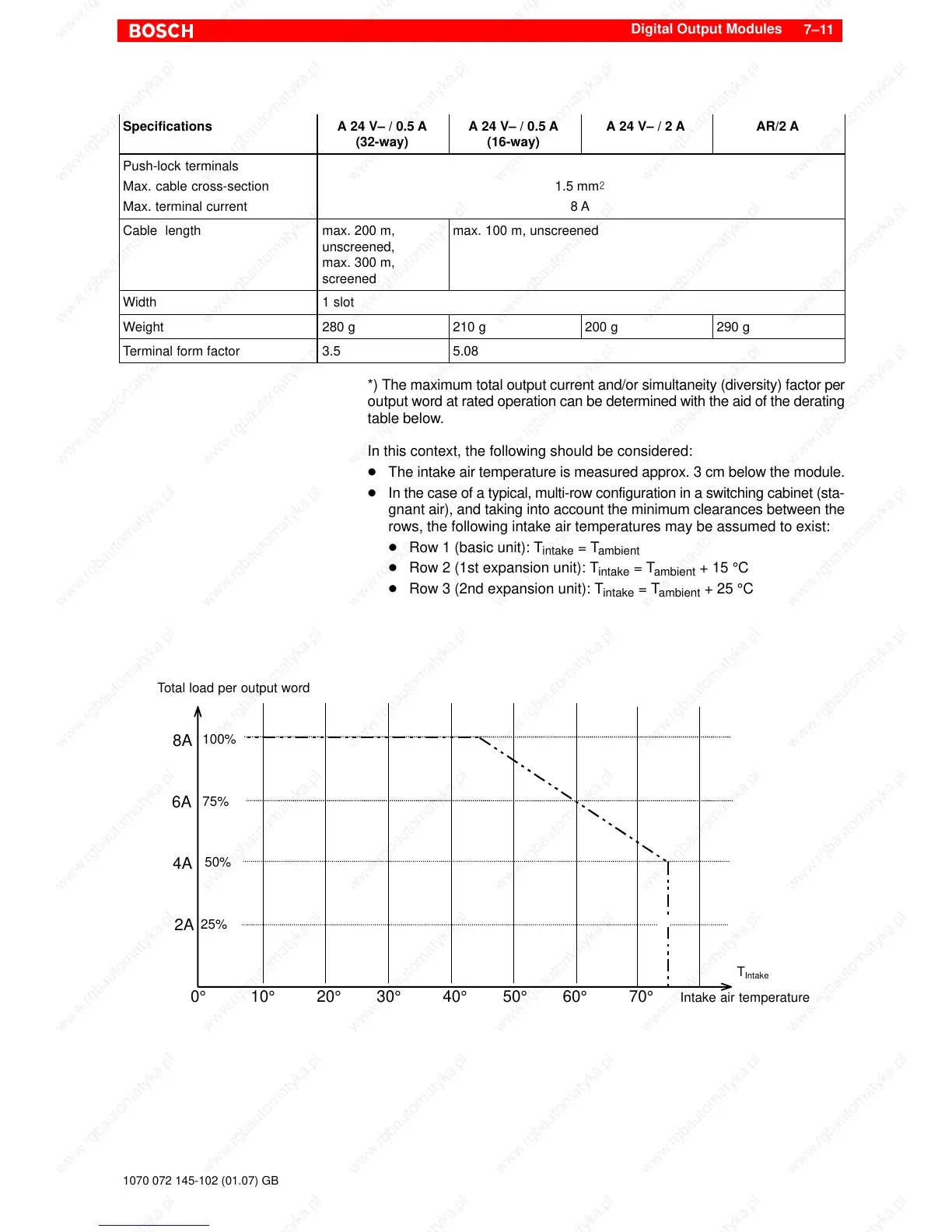
*) The maximum total output current and/or simultaneity (diversity) factor per
output word at rated operation can be determined with the aid of the derating
table below.
In this context, the following should be considered:
D The intake air temperature is measured approx. 3 cm below the module.
D In the case of a typical, multi-row configuration in a switching cabinet (sta-
gnant air), and taking into account the minimum clearances between the
rows, the following intake air temperatures may be assumed to exist:
D Row 1 (basic unit): T
intake
= T
ambient
D Row 2 (1st expansion unit): T
intake
= T
ambient
+ 15 °C
D Row 3 (2nd expansion unit): T
intake
= T
ambient
+ 25 °C
0° 10° 20° 30° 40° 50° 60°
25%
2A
50%
4A
75%
6A
100%
8A
Intake air temperature
T
Intake
70°
Total load per output word