| 1 689 989 298 2017-03-08Robert Bosch GmbH
Technical data | FSA 760 Edition | 29
8.1.5 Oscilloscope measuring functions
Measuring functions Measuring range
1)
Sensors
Secondary voltage 5 kV – 50 kV
2)
Secondary sensor
Primary voltage 20 V – 500 V
2)
Primary connecting
cable (UNI 4)
Voltage 200 mV – 200 V
2)
5 V – 500 V
2)
Multi measuring
cable CH1 / CH2
Measurement lead
with voltage divider
AC coupling 200 mV – 5V Connecting cable
B+/B–
Current 2 A
5 A
10 A
20 A
30 A
Current clamp 30 A
Current 50 A
100 A
200 A
1000 A
Current clamp
1000 A
1)
The measuring range is positive or negative depending on the
zero line.
2)
The measuring range is greater than the permissible
measurement voltage
8.1.6 Oscilloscope functions andspecificationsxxx
Function Specification
Input coupling CH1/CH2 AC/DC
Input impedance CH1/CH2
(relative to ground)
1 MOhm
Input impedance
CH1/CH2
(galvanically insulated)
1 MOhm (5 — 200 V)
10 MOhm (200 mV — 2 V)
Input impedance CH2
(switchover)
4 MOhm
Bandwidth CH1
(galvanically insulated)
> 5 kHz = 200 mV – 2 V
> 25 kHz = 5 V – 200 V
Bandwidth CH1 (relative to
ground)
> 1 MHz = 200 mV – 2 V
> 5 MHz = 5 V – 200 V
Bandwidth CH2 (relative to
ground)
> 1 MHz = 200 mV – 2 V
> 5 MHz = 5 V – 200 V
Bandwidth
Measurement lead with voltage
divider
> 500 kHz
Bandwidth CH2 (differential
measurement)
> 30 kHZ
Bandwidth 1000 A current clamp > 1 kHz
Bandwidth 30 A current clamp > 50 kHz
Bandwidth secondary sensor > 1 MHz
Bandwidth
Primary connecting cable (UNI 4)
> 100 kHz (20 V)
> 1 MHz (50 V – 500 V)
Time ranges (relative to 500
scanning points)
10 µs – 100 s
Time ranges (relative to 1
scanning point)
20 ns – 200 ms
Time basis accuracy 0,01 %
Vertical accuracy
Device without sensors
±2 % of reading
±0,3 % of measuring range
(Offset error for ranges > 1 V)
or ±5 mV
(offset error for ranges 200
mV – 1V)
Vertical resolution 10 bit
Function Specification
Memory depth 1 Mega scan values or 50
curves
Scan rate per channel 50 Ms/s
8.2 Signal generator
Function Specification
Amplitude ‑10 V – 12 V
(load < 10 mA) to ground
Signal shapes DC, sinus, triangle, square
Frequency range 1 Hz – 1 kHz
Output current
(load‑dependent)
30 mA – 75 mA
Impedance ca. 60 Ohm
Symmetry 10 % – 90 % (triangle, square)
Curve generation Output rate up to 100,000 values/s,
Resolution 8 bit,
Y‑full range adjustable ( bit),
Unipolar / bipolar mode.
Short‑circuit resistance
to interference voltage
< 50 V static
Short‑circuit resistance
to interference voltage
< 500 V / 1 ms dynamic
R Automatically switched filter and damping elements
for improvement of signal quality.
R Automatic cutoff at short circuit, interference
voltage detection at start of signal generator.
8.3 Power pack
Function Specification
Input voltage: 90 VAC – 264 VAC
Input frequency 47 Hz – 63 Hz
Output voltage 15 V
Operating temperature 0 °C – 40 °C
8.4 Noise emissions
< 70 dB(A)
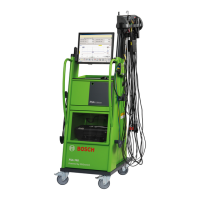
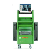
8.5 Dimensions and weights
Function Spezifikation
Dimensions H x B x T: 1785 x 680 x 670 mm
Weight 91 kg
8.6 Temperature and humidity
Designation Value/Range
Operating temperature 5 °C – 40 °C
41 °F – 104 °F
Storage temperature 5 °C – 40 °C
41 °F – 104 °F
Relative humidity in operation 90 % non‑condensing
en
 Loading...