12.4 Facility Pre-Installation Summary
12.4.1 Overview of Mains Power Supply and Interlocks
Installation Suggestion
This overview provides suggestions on how to fulfill the ExacTrac requirements from the previous
chapters. Local regulatory requirements and your specific needs can lead to a dif
ferent solution for
implementing power supply switching and interlock inputs and outputs.
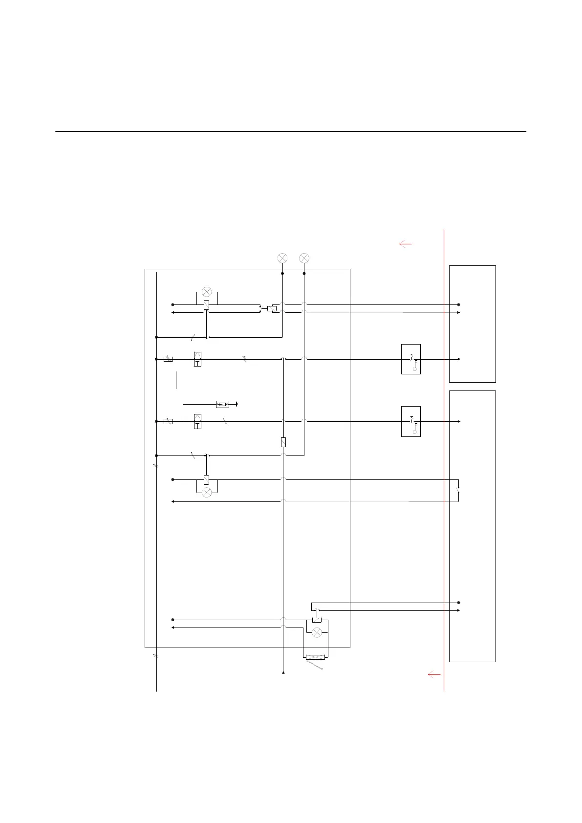
The following diagram shows an example of an electrical schematic for the pre-installed power
supply and interlock circuits:
EXAMPLE
Computer Cabinet
[1.0]
ExacTrac
X-Ray enable
Customer warning lights.
X-Ray Generator energized.
from
emergency-off
circuit
door interlock
F 50A/50Hz
indolent
Fi
0.03A
F 16A/50Hz
Fi
0.03A
Overvoltage
protection
Typ 2 / Class II
TN Star Network
24V DC 24V DC
230V AC
Customer warning lights .
ExacTrac X-Ray in use.
wire cross section:
max. 25 mm²
wire cross section:
2,5 ... max. 16 mm²
On
Off
On
Off
230V AC
L, N & G
400V AC
L1, L2, L3, N & G
Flexible
cable
Flexible
cable
wire cross section:
1 mm²
wire cross section:
1 mm²
X-Ray Generator
[1.0]
Customer supplied including
cabling to connection point at
Computer- and Generator
cabinet x-ray plus 3 m
230V AC
230V AC
ExacTrac
X-Ray enable
24V DC
(**)
(*)
wire cross section:
1 mm²
12V DC
(*) The power shut down is not an ExacTrac installation requirement.
Please check if your local regulations require it.
(**) ExacTrac can also provide a 12 Volts DC signal.
Option to use the bunker warning lights instead of the ones provided with ExacTrac.
Figure 44
APPENDIX
Site Planning Manual Rev. 1.0 ExacTrac Ver. 6.x 109