F1: Generator Fusing
The F1 generator fusing is a part of building installation and is mounted in the distribution box.
The fuses are small compared to the operating current and operating power. This can be contrary
to the cross-sectional diameter of the power cables that are chosen for the required power supply
resistance.
NOTE: The X-ray generator(s) can only take this high current for a short period of time.
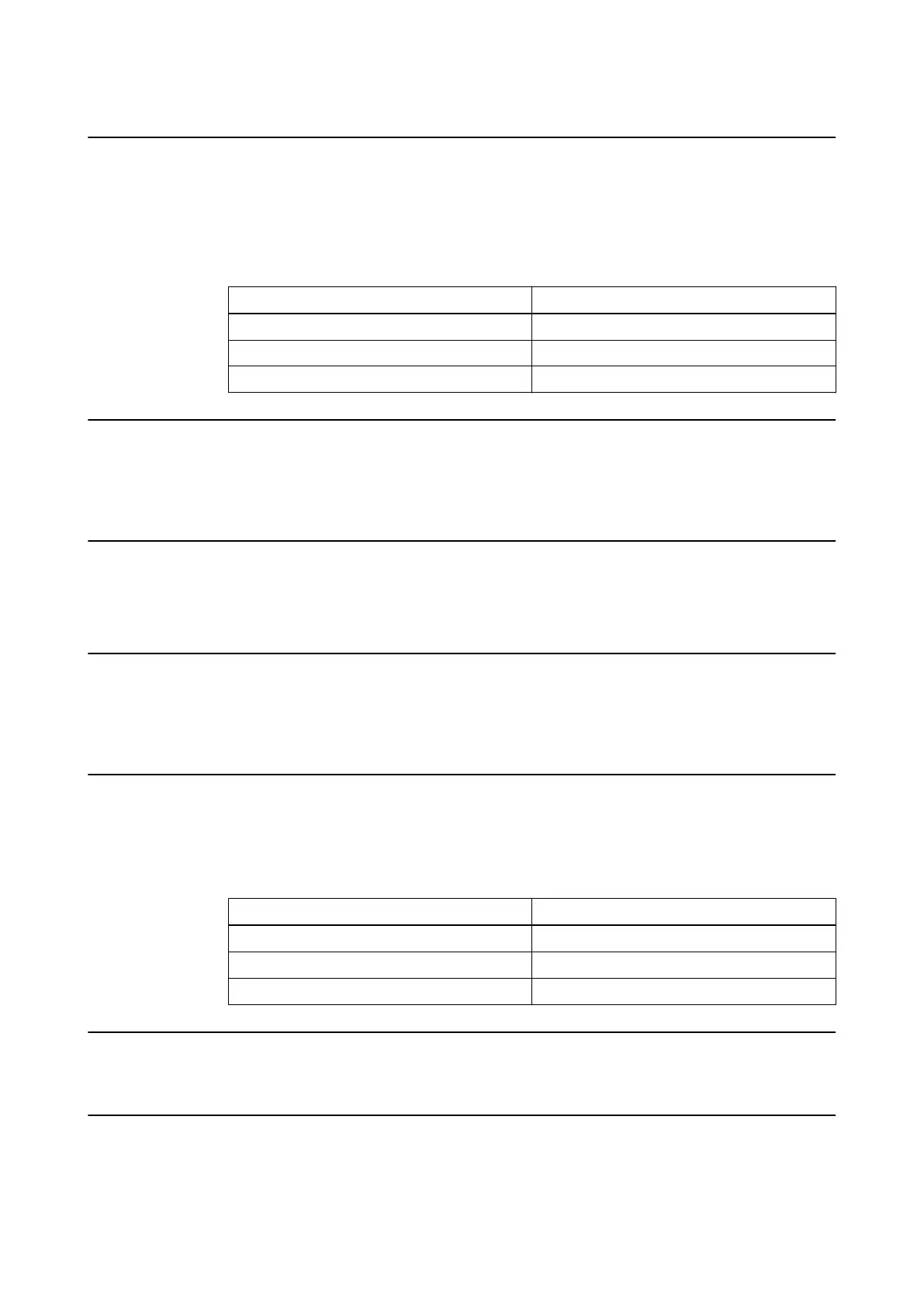
Mains Supply Fuse Slow Blow A
380/400 V 50
420/440/480 V 50
208/220 V 100
F2: Control Fuse
The F2 control fuse is a part of the building installation and is mounted in the distribution box.
The auxiliary circuit for controlling the main contactor must be protected by a 10 A fuse or circuit
breaker.
S0: Installation Switch/Emergency OFF Switch
The installation switch is part of the building installation and is connected to the distribution box.
NOTE: The switch must be mounted in the vicinity of the generator control console.
K1: Main Contactor
The main contactor is a part of the building installation and is mounted in the distribution box.
One 63 A contactor with an auxiliary contact and coil is recommended for the EDITOR HFe dual
generator
.
F3: Current Operated Earth-Leakage Circuit Breaker
The earth-leakage circuit breaker is a part of the building installation and is mounted in the
distribution box.
One/DC ELCB (earth-leakage circuit breaker) with a leakage current of 30 mA is recommended
for the EDITOR HFe dual generator
.
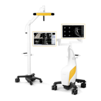
Main Supply ELCB
380/400 V 63 A
420/440/480 V 63 A
208/220 V 100 A
N: Main Neutral Point Bar
The main neutral point bar is part of the building installation and is mounted in the distribution box.
PE: Main Safety Earth Bar
The main safety earth bar is part of the building installation and is mounted in the distribution box.
Facility Pre-Installation Summary
112 Site Planning Manual Rev. 1.0
ExacTrac Ver. 6.x