13
ECU Mounting
The ECU should be mounted in a location free from moisture and excessive heat. Note: the ECU body may
generate some heat during normal operation.
System Connection
Refer to the vehicle manufacturers bodybuilder guidelines for installation procedures and connectivity in all
applications. Ensure the power and ignition connections are fused at source. For system connectivity, refer to System
Drawing in section 5.1.
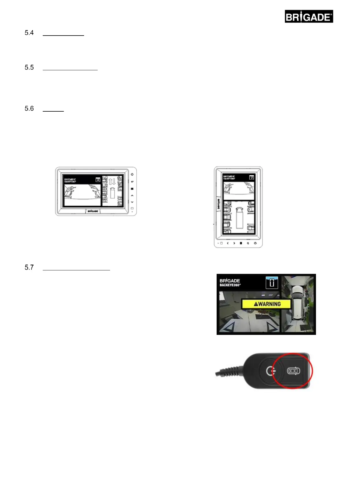
Monitor
The monitor should be fixed in a suitable location for the operator and in line with any current legislation/regulations.
The system can be installed in landscape or portrait view orientations therefore it may be necessary to rotate the
monitor by 90°.
Default System displayed on a monitor in Landscape
position
Portrait configuration displayed on a monitor rotated
for correct view orientation
With the system connected as per Section 5.1, turn the vehicle ignition
on and check the image output on the monitor.
Note: The “WARNING” message will be displayed until a
calibration has been completed for the first time.
Pressing the View Select Button on the Set-up & View Select Button will
cycle through the single camera views. This would be a good time to
check the camera positioning as per Section 5.2.