14
Vehicle Calibration
To create a usable and reliable 360° surround view image a full calibration needs to be performed. As every vehicle
and installation is different from the next, the camera positions must be calibrated using the Backeye 360° Calibration
Kit. The procedure involves the following steps:
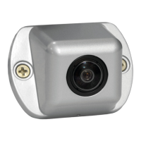
▪ Camera installation on vehicle.
▪ Place Calibration Mats around vehicle.
▪ Capture vehicle images using Calibration Tool.
▪ Calibrate camera positions using Calibration Software.
▪ Upload calibration data to the Backeye 360° ECU.
▪ Verify Calibration result.
Calibration Environment
A minimum 2m perimeter is needed around the vehicle. The floor needs to be a flat surface as calibration may not
be possible if the ground is uneven.
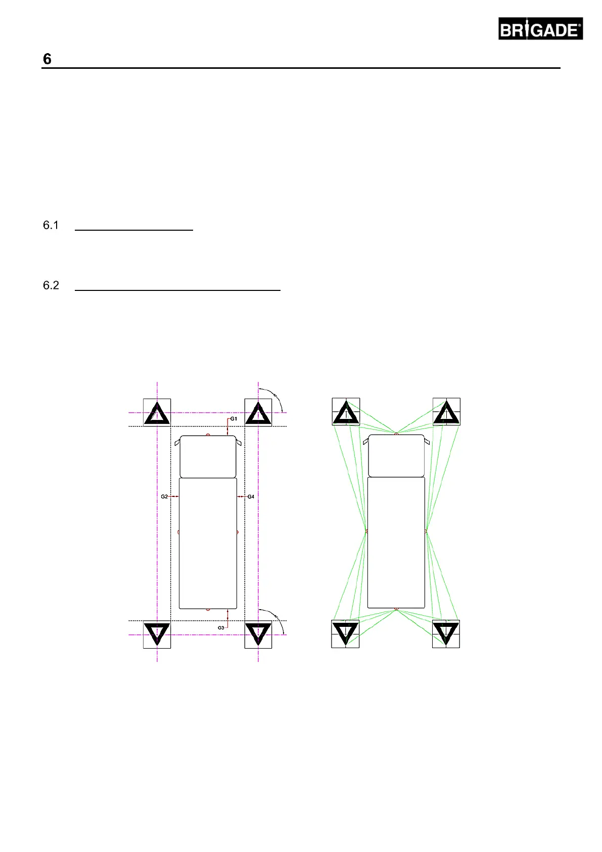
Calibration Pattern and Vehicle Alignment
The Calibration Mats listed in Section 3.2.2 should be placed symmetrically around the vehicle as shown in the image
below (left). The Calibration Matts should ideally be placed as close to the cameras as possible however this may
vary for different vehicle and installation types, as long as each camera is able to see all three points of the two
triangles in the cameras field of view as shown in the image below (right) the system will calibrate. The more
accurately the Calibration Matts are positioned around the vehicle, the better the final result will be. Chalk line, string
or laser tools are recommended for improved accuracy.
Note: it is imperative that the Calibration Mats are laid out as shown above, if the orientation of the mats is
different (e.g. they are rotated through 90°) the system will not calibrate correctly.