18
Calibration Control Points
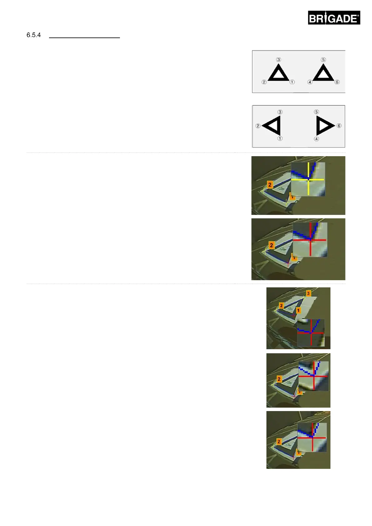
The triangles in the calibration pattern are automatically detected and the
control points are displayed. The software automatically detects the
corners of the triangles and derives the coordinates of each image when
loaded. The order of the control points starts from the triangle point closest
to the vehicle and working clockwise to the other two points. Calibration is
not possible if the order of the control points is not correct.
WARNING: Ensure the control points are selected in the correct
order as shown. Anything other than the above will result in
calibration failure.
Front & Rear Camera View
Left & Right Camera View
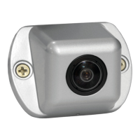
It may be necessary to adjust the control points once the images have been
loaded. The control point image will enlarge when the mouse curser is
moved to the control point. This enables the control points to be positioned
accurately. Left click the control point that needs modifying. The selected
control point crosshair will turn red. To deselect the control point, just left
click anywhere else other than the selected control point.
Align the control point to the outermost corner as shown below, aligning the
blue lines to the triangle. The images to the right show before and after
alignment. It is recommended to move the control point outside of the
triangle to leave a clear gap between it and the triangle then work the point
back towards the triangle until it meets the outer edge of the triangle. Check
and modify all six control points for each camera.
Useful hints:
• With a control point selected, using the arrow buttons on the PC keyboard
will move the crosshair one pixel at a time in the given direction allowing
much finer and more controlled adjustment.
• Double clicking in the individual camera image screen will make that image
full screen, making small adjustments much easier.