EasyManuals Logo

Brocade Communications Systems MLX Series Hardware Installation Guide

Brocade Communications Systems MLX Series
344 pages
To Next Page IconTo Next Page
To Previous Page IconTo Previous Page
Page #294 background imageLoading...
Page #294 background image
278 Brocade MLX Series and NetIron XMR Hardware Installation Guide
53-1003821-01
Replacing fan assemblies
7
4. Insert the new fan assembly into the fan slot and push the assembly in until the faceplate is
flush with the router. Pushing the fan assembly in seats the fan connector in the router
connector.
5. Secure the fan assembly to the router by replacing and tightening the four screws (on the
upper eight fan assemblies) and the two screws (on the lower two fan assemblies).
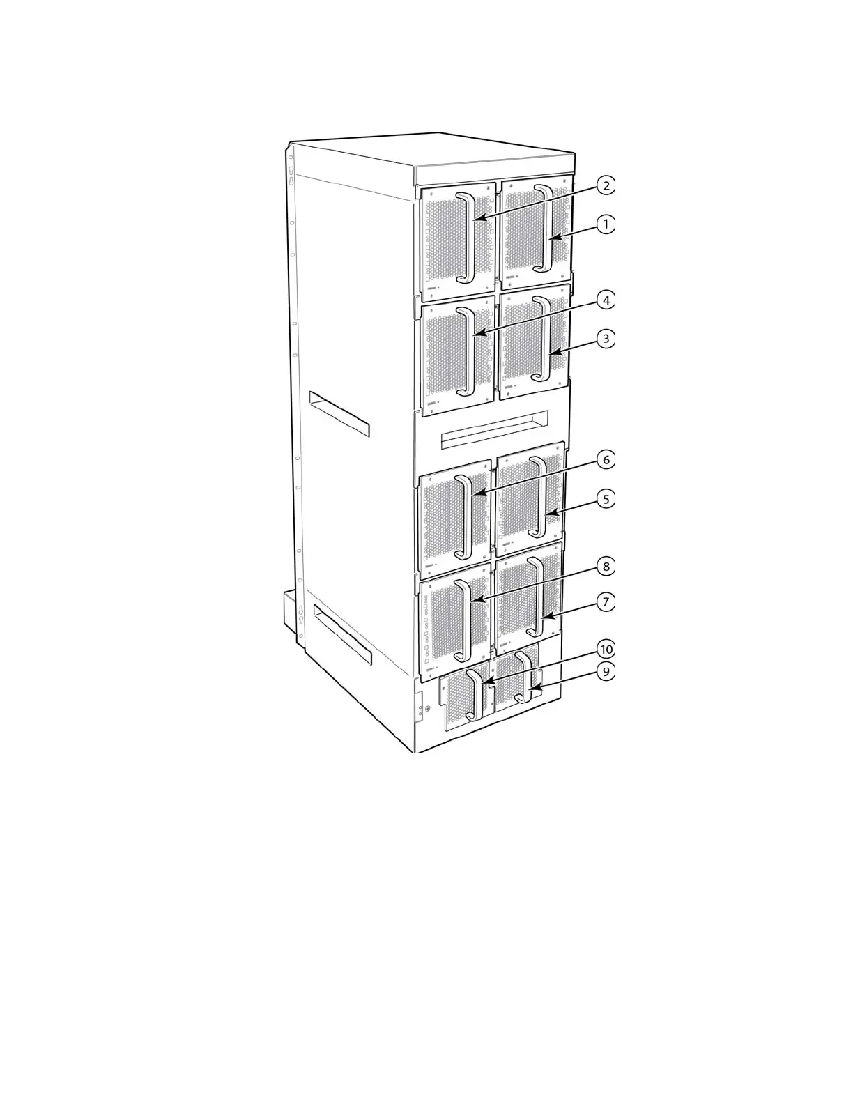
1 Fan module 1 6 Fan module 6
2 Fan module 2 7 Fan module 7
3 Fan module 3 8 Fan module 8
4 Fan module 4 9 Fan module 9
5 Fan module 5 10 Fan module 10

Table of Contents

Other manuals for Brocade Communications Systems MLX Series

Questions and Answers:

Question and Answer IconNeed help?

Do you have a question about the Brocade Communications Systems MLX Series and is the answer not in the manual?

Brocade Communications Systems MLX Series Specifications

General IconGeneral
BrandBrocade Communications Systems
ModelMLX Series
CategoryNetwork Router
LanguageEnglish

Related product manuals