150 Brocade MLX Series and NetIron XMR Hardware Installation Guide
53-1003821-01
Installing a NetIron XMR 8000 router
3
4. Connect the -48V cable to the negative terminal on the power supply and the 0V cable to the
positive terminal on your DC power source.
DC return must be isolated from the device ground (DC-I) when connecting to the power supply.
5. Replace the transparent cover.
This equipment installation must meet NEC/CEC code requirements. Consult local authorities for
regulations.
Final steps
Follow these steps in the order listed to complete the installation:
• “Attaching a management station”
• “Activating the power source”
• “Verifying proper operation”
Installing a NetIron XMR 8000 router
The following sections describe how to install a NetIron XMR 8000 router.
Preparing the installation site
Before installing the router, plan the location and orientation relative to other devices and
equipment. For cooling purposes, allow a minimum of six inches of space between the sides, front,
and the back of the router and walls or other obstructions. If a router is installed in a perforated
enclosure, the perforations must cover at least 60 percent of the surface.
Ensure that the proper power and network cabling is installed in the site. For information on
cabling, refer to “Installing NetIron XMR 8000 router power supplies” on page 156, and “Attaching
a management station” on page 193.
Unpacking a NetIron XMR 8000 router
The NetIron XMR 8000 router ships with the following items:
• Router chassis with the appropriate number of switch fabric modules already installed in the
slot marked SF and a slot blank installed in all other module slots.
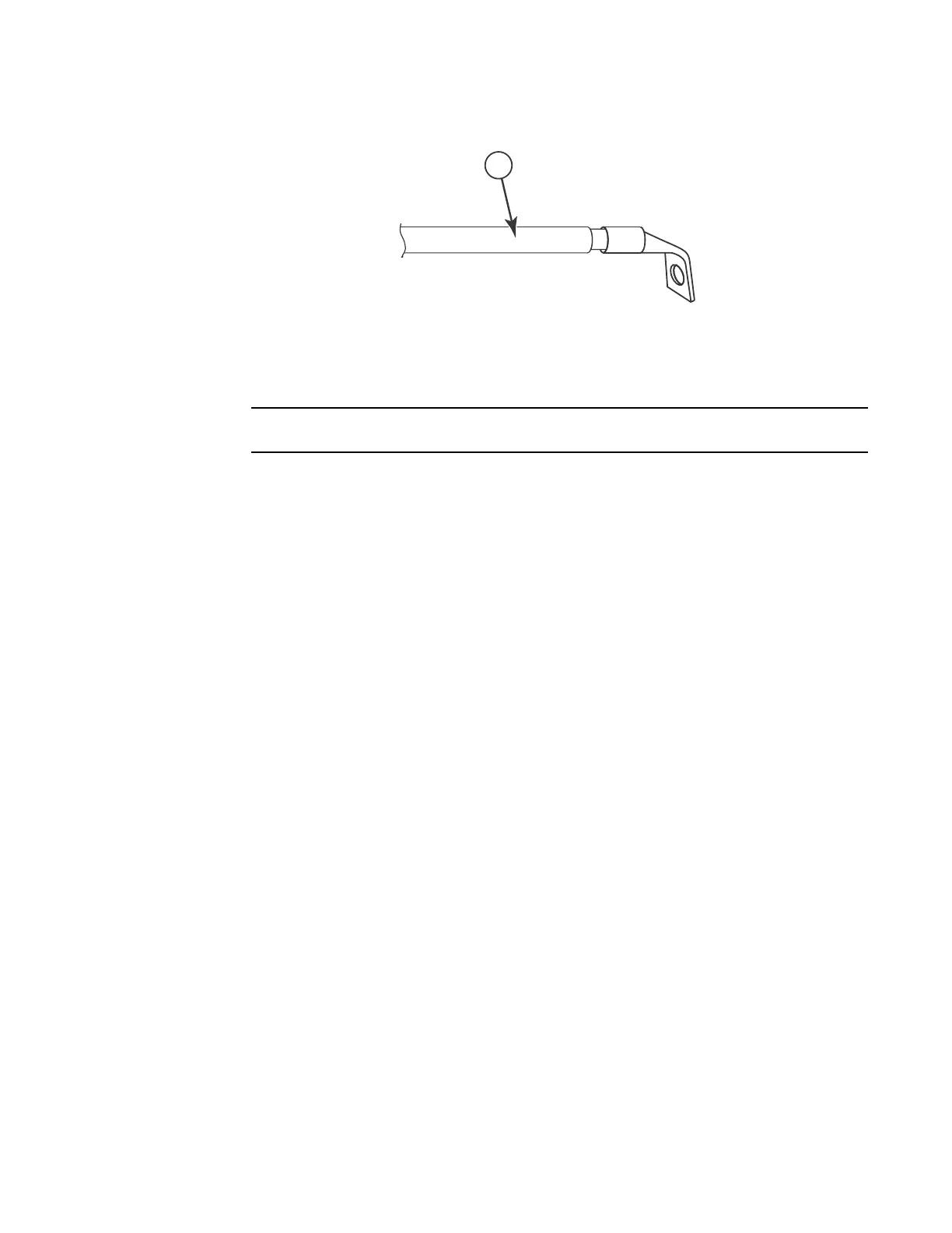
1 #8 AWG power supply wire
 Loading...
